α
Simple Application Controllers
Function Block Diagram (FBD) Operation 6
6-8
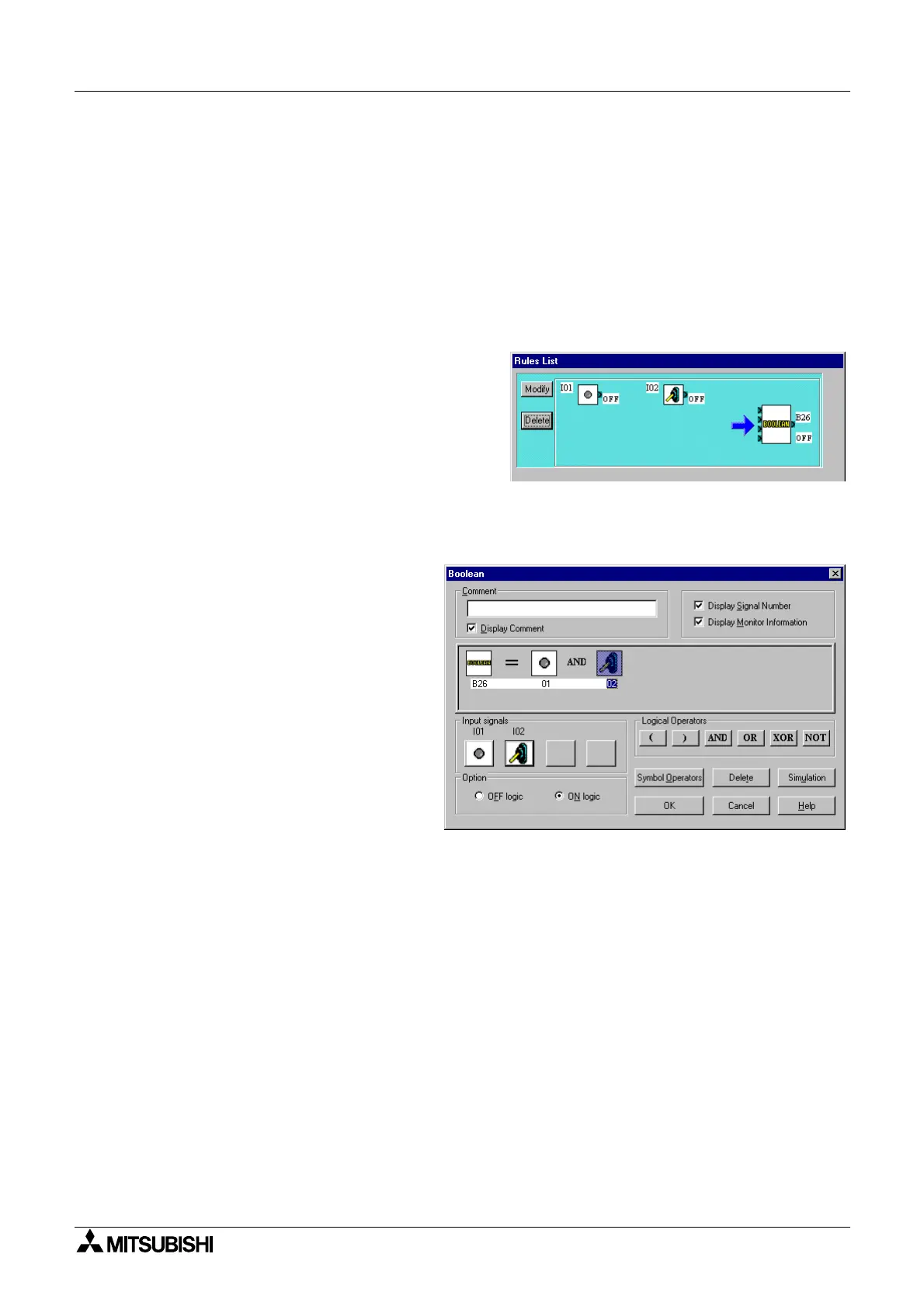
6.5.7 Setting Parameters
Set parameters for the Function Blocks and set up Lo
ic functions for the Boolean parameter
in this screen. A red arrow will appear above the Function Block that should have its
parameters set next.
Double click on the Function Block to open the parameter dialo
box and enter the parameters
as re
uired. A Boolean Function Block will alwa
s appear in this screen to enable the user to
emplo
Lo
ic Operations. The lo
ic must be set for the Boolean operation.
The lo
ic can be
set so that the whenever the input is On, the Boolean Block is On. This makes the operation of
the Boolean function transparent
.
The lo
ic can be set two wa
s - the Set Rule or
the Set b
Lo
ic option. Set Rule allows the
user to set the si
nals in as man
non-
conflictin
options as desired and the lo
ic will
be
enerated b
the VLS software. Click on the
si
nals and function blocks to turn the device
On or Off and accept with the Set Rule button
when finished. Set as man
Rules for each
situation as necessar
.
The Set b
Lo
ic option allows the user
to write a lo
ic e
uation usin
the AND,
OR, XOR, NOT, and operands.
6.5.8 Operation Check
Check the operation of the circuit b
turnin
the Input Si
nals On and Off. The status of the
outputs and the current and set values for each block will be displa
ed. The wire connected to
an output pin which is On
Si
nal or Function Block
will chan
e to a red color.
When finished with the operation check, press the Finish button to place the completed circuit
on the FBD base or Cancel to return to the FBD base in its ori
inal condition.

 Loading...