EasyManuals Logo

Mitsubishi FX3U User Manual

Mitsubishi FX3U
260 pages
To Next Page IconTo Next Page
To Previous Page IconTo Previous Page
Page #168 background imageLoading...
Page #168 background image
13 Example of Communication between Master Station
13.2 When Remote Net Ver. 2 Mode is Used
162
FX3U-16CCL-M User's Manual
13.2.6 Execution of data link
Turn on the power of the remote device stations first, turn on the power of the master station, then start the
data link.
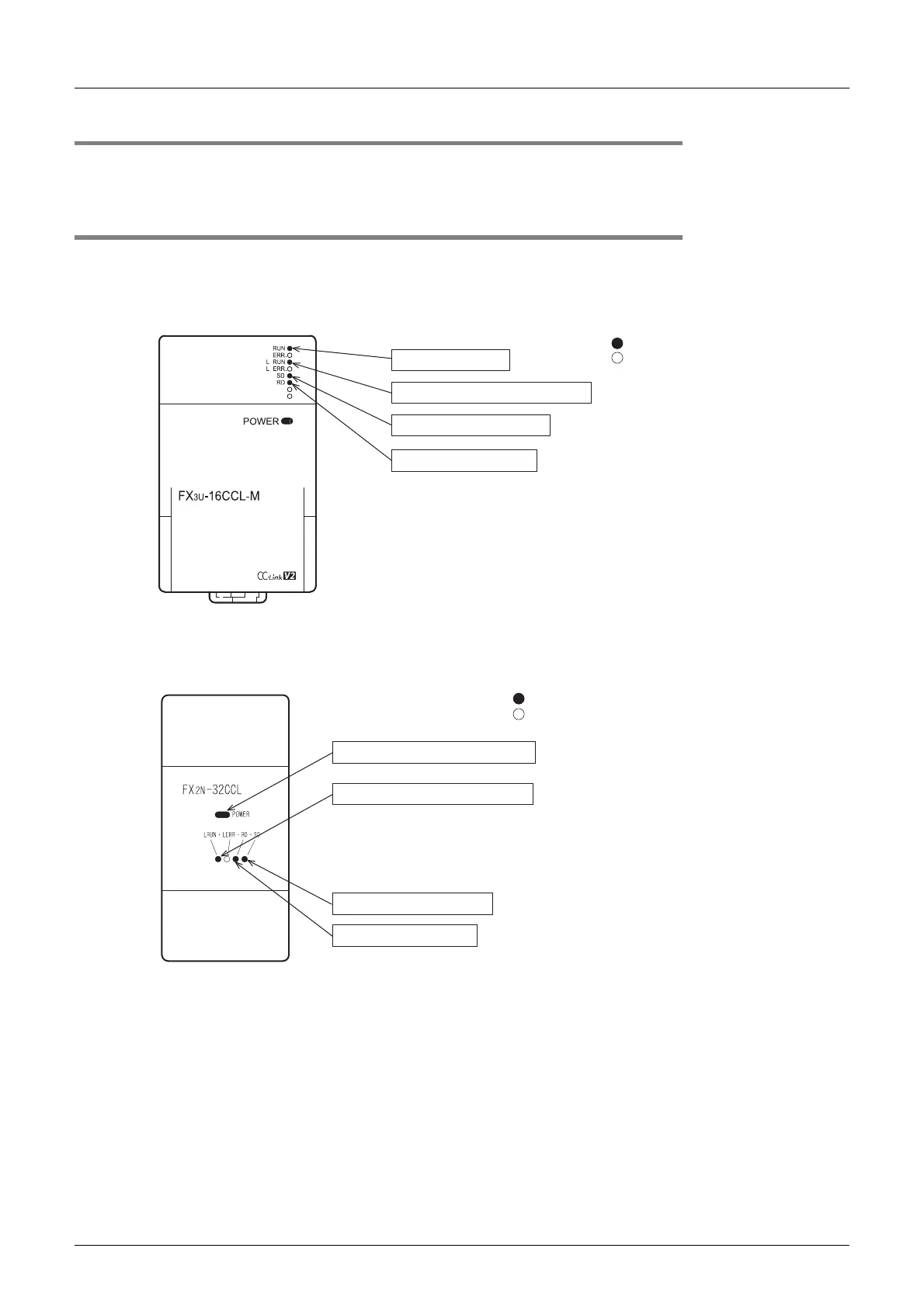
13.2.7 Confirmation of operation by LED indication
The figures below show the LED indication status in the master station and the remote device stations while
the data link is normally proceeding.
LED indication in the master station
Make sure that the LED indication status is as shown below.
LED indication in the remote device station
Make sure that the LED indication status is as shown below.
-FX
2N-32CCL
The unit is normal.
Data link is normally proceeding.
Data is being transmitted.
Data is being received.
: On
: Of
f
5 V DC is supplied from the PLC.
Data link is normally proceeding.
Data is being transmitted.
Data is being received.
: On
: Of
f

Table of Contents

Other manuals for Mitsubishi FX3U

Questions and Answers:

Question and Answer IconNeed help?

Do you have a question about the Mitsubishi FX3U and is the answer not in the manual?

Mitsubishi FX3U Specifications

General IconGeneral
SeriesFX3U
Program Capacity64k steps
TypePLC
Power SupplyAC: 100-240V, DC: 24V
I/O PointsUp to 384 points
CommunicationRS-232C, USB, Ethernet
ExpansionSupports multiple expansion modules including I/O, analog, and communication modules
Programming LanguageLadder Logic, SFC, Function Block Diagram
High-speed Processing0.065 μs per basic instruction
Analog I/OAvailable with expansion modules
Positioning ControlUp to 3 axes of positioning control
Weight0.3 kg (Main unit)

Related product manuals