5 Wiring
5.2 CC-Link Wiring
37
FX3U-16CCL-M User's Manual
1
Introduction
2
Specification
3
System
Configuration
4
Installation
5
Wiring
6
Introduction of
Functions
7
Data Link
Processing
Time
8
Parameter
Setting
9
Data Link
Procedure
10
Buffer Memory
5.2 CC-Link Wiring
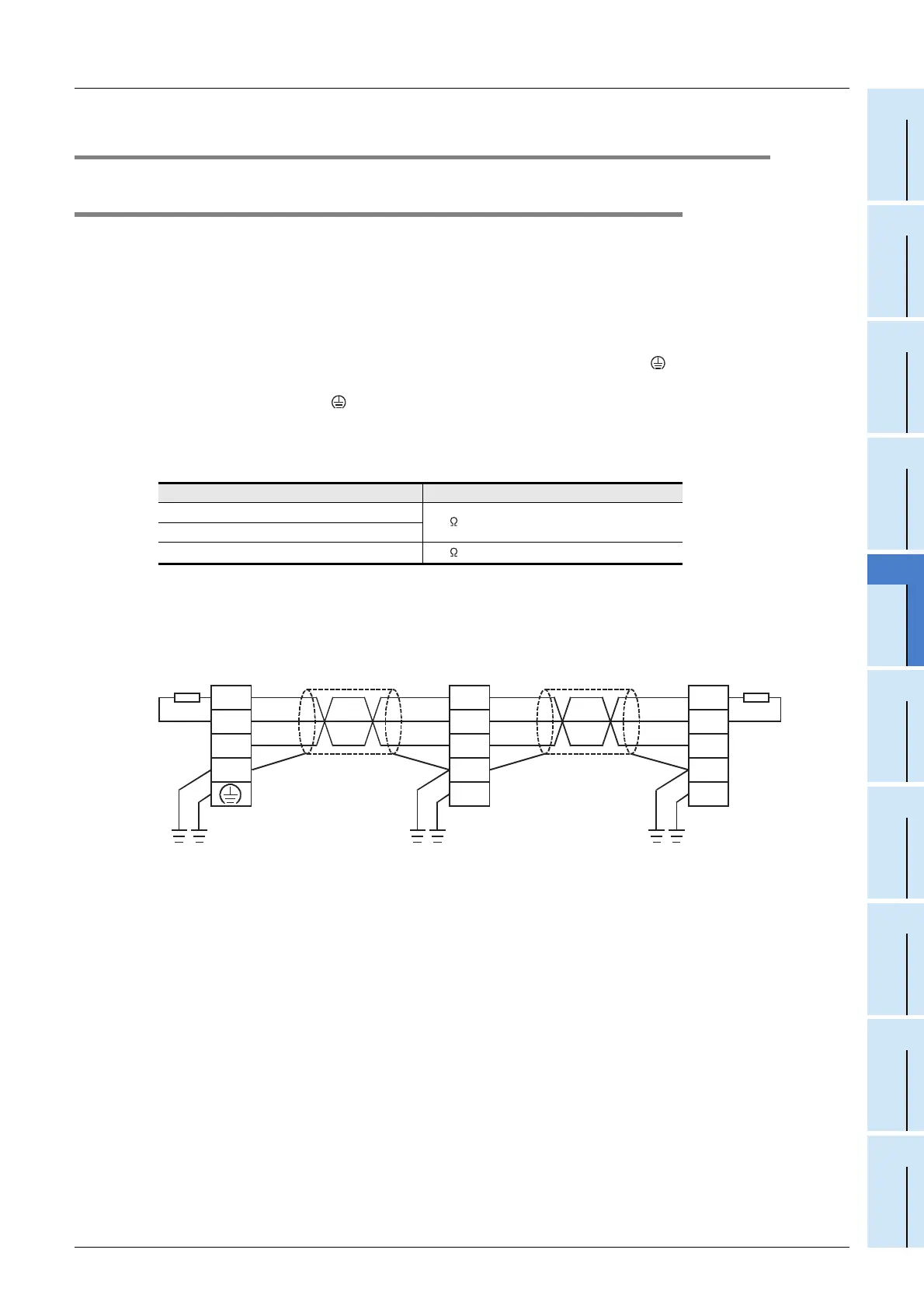
5.2.1 Unit wiring with CC-Link dedicated cables
This subsection describes the connection method of CC-Link dedicated cables.
→ For details on CC-Link dedicated cables, refer to Section 2.6.
• CC-Link dedicated cables, Ver. 1.10 compatible CC-Link dedicated cables and CC-Link dedicated high-
performance cables cannot be used together.
If used together, normal data transmission cannot be guaranteed.
• The cables can be connected without regard to the station number.
• The shielded CC-Link dedicated cable should connected to the [SLD] and "[ ] or [FG]" terminals in each
unit, and both ends should have Class D grounding.
The terminals [SLD] and "[ ] or [FG]" are connected to each other inside the unit.
• Connect the supplied "terminal resistors" to FX
3U-16CCL-M at both ends of the CC-Link system.
Connect the terminal resistors between [DA] and [DB].
• In the CC-Link system, the terminal resistor to be connected varies depending on the cable used.
• The FX
3U-16CCL-M can be connected besides to the both ends.
• Star connection is not allowed.
• The figure below shows the connection method.
• In the CC-Link system, the maximum transmission and cable length distance between stations that can be
set varies depending on the transmission speed.
→ For the maximum transmission and cable length distance between stations, refer to Section 2.5.
Cable type Terminal resistor
CC-Link dedicated cable
110 1/2W (brown, brown and brown)
CC-Link dedicated high-performance cable
Ver. 1.10 compatible CC-Link dedicated cable
130 1/2W (brown, orange and brown)
(Blue)
(White)
(Yellow)
(Blue)
(White)
(Yellow)
(Blue)
(White)
(Yellow)
(Blue)
(White)
(Yellow)
DA
DB
DG
SLD
FG
DA
DB
DG
SLD
DA
DB
DG
SLD
FG
CC-Link
Dedicated
Cable
CC-Link
Dedicated
Cable
Other
station
Termi-
nating
resistor
Termi-
nating
resistor
FX3U-16CCL-M
Other
station

 Loading...


