6 Introduction of Functions
6.2 Basic Functions
43
FX3U-16CCL-M User's Manual
1
Introduction
2
Specification
3
System
Configuration
4
Installation
5
Wiring
6
Introduction of
Functions
7
Data Link
Processing
Time
8
Parameter
Setting
9
Data Link
Procedure
10
Buffer Memory
Remote input
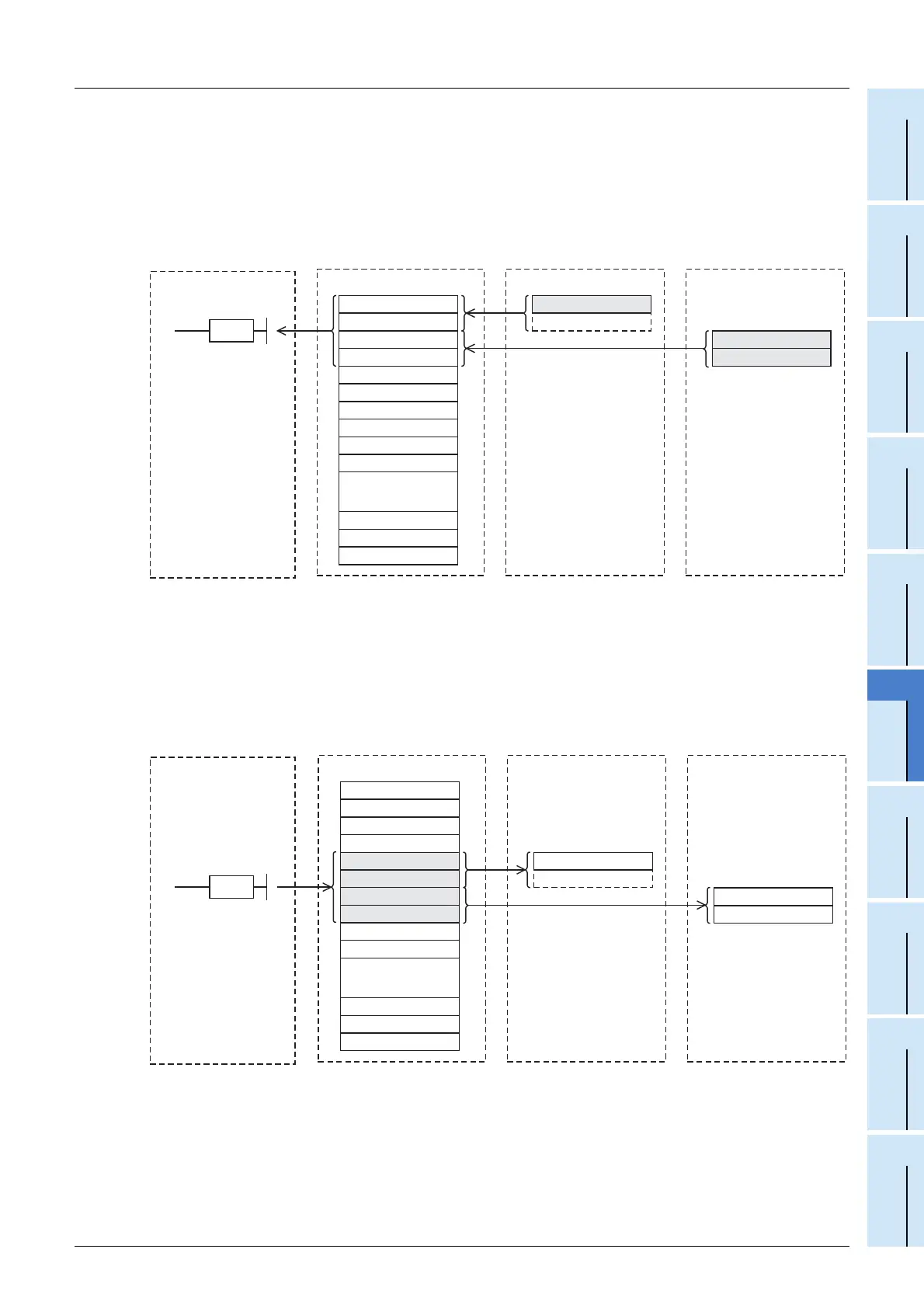
3) The input status of the remote I/O stations is automatically (for each link scan) stored in the buffer
memory "remote input (RX)" in the master station.
4) The PLC receives the input status stored in the buffer memory "remote input (RX)" using the FROM
instruction.
Remote output
5) The PLC writes the ON/OFF information output from the remote I/O station to the buffer memory "remote
output (RY)" using the TO instruction.
6) The output status stored in the buffer memory "remote output (RY)" is automatically (for each link scan)
output from the remote I/O stations.
Master station
Remote I/O station
(Station No. 1:
Occupies 1 station)
RX F to RX 0
RX 1F to RX 10
RX 2F to RX 20
RX 3F to RX 30
RX 4F to RX 40
RX 5F to RX 50
RX 6F to RX 60
RX 7F to RX 70
RX 8F to RX 80
RX 9F to RX 90
RX1EF to RX1E0
RX1FF to RX1F0
...
Remote input (RX)
X0F to X00
X0F to X00
X1F to X10
Remote I/O station
(Station No. 2:
Occupies 1 station)
RX1DF to RX1D0
32-point unit16-point unit
3)
3)
FROM
4)
PLC
Master station
Remote I/O station
(Station No. 3:
Occupies 1 station)
RY F to RY 0
RY 1F to RY 10
RY 2F to RY 20
RY 3F to RY 30
RY 4F to RY 40
RY 5F to RY 50
RY 6F to RY 60
RY 7F to RY 70
RY 8F to RY 80
RY 9F to RY 90
RY1EF to RY1E0
RY1FF to RY1F0
...
Remote output (RY)
Y0F to Y00
Y0F to Y00
Y1F to Y10
Remote I/O station
(Station No. 4:
Occupies 1 station)
RY1DF to RY1D0
TO
5)
PLC
6)
6)
16-point unit
32-point unit

 Loading...


