B-49
6 Changing Input Characteristics
6.1 Procedure for Changing Input Characteristics
A
Common Items
B
FX
3UC
-4AD
C
FX
3U
-4AD-ADP
D
FX
3U
-4DA-ADP
E
FX
3U
-4AD-PT
-ADP
F
FX
3U
-4AD-TC
-ADP
G
PID Instruction
(FNC 88)
FX
3U
/FX
3UC
Series PLC User's Manual - Analog Control Edition
FX3UC-4AD (4-channel Analog Input)
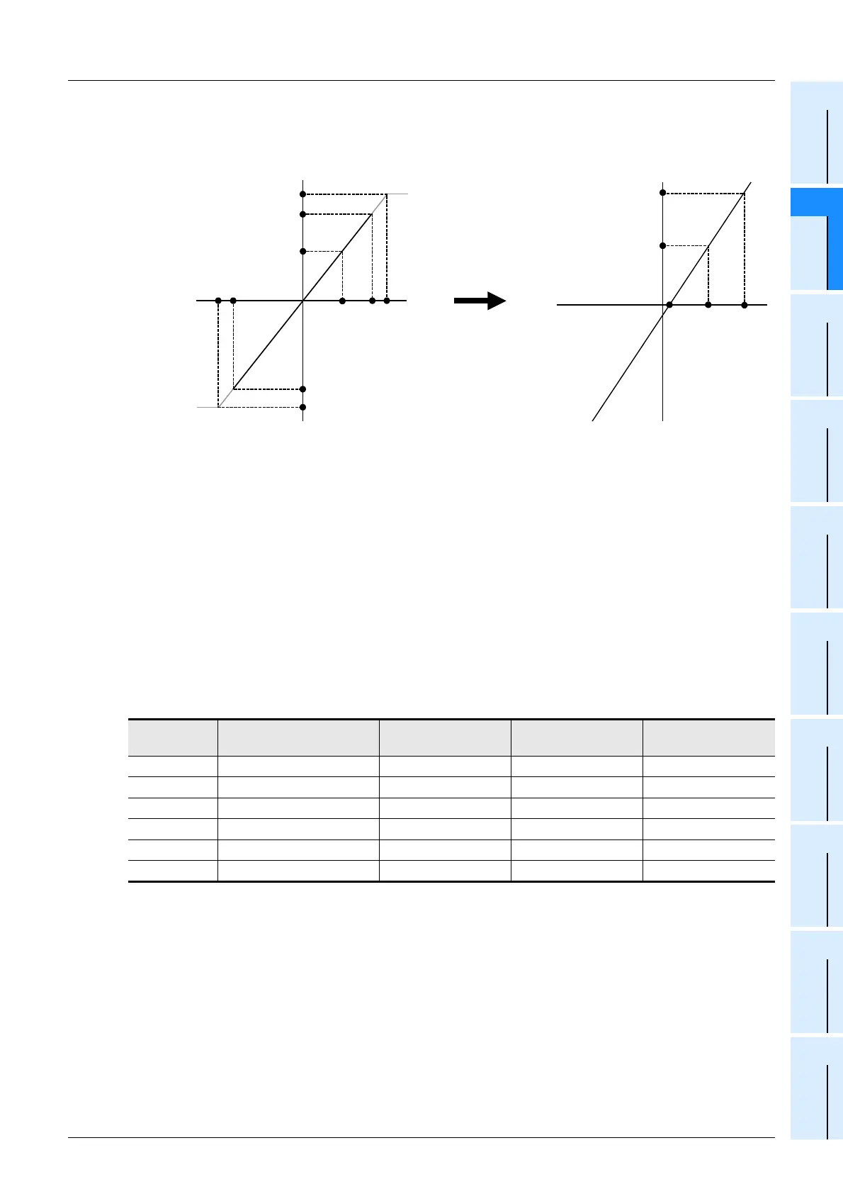
Example: To output digital values in the range from 0 to 10000 by inputting the voltage in the range
from 1V DC to 5V DC:
3 Determine the offset data.
Determine the analog input value (offset data) for digital output value of "0".
Set the analog input value in mV for the voltage input mode, and set the analog input value in µA
for the current input mode.
Example: To set the offset value of 1 V, set 1,000 mV.
→ For a detailed description of offset data, refer to Subsection 5.4.14.
4 Determine the gain data.
Determine the analog input value so that the digital output value is equal to the gain reference
value of each input mode.
The following table shows the gain reference value of each input mode:
Set the analog input value in mV for the voltage input mode, and set the analog input value in µA
for the current input mode.
Example: To set the gain value of 3 V, set 3000 mV.
→ For a detailed description of gain data, refer to Subsection 5.4.14.
Numeric
value
Input mode Analog input range Gain standard value Initial value
0 Voltage input mode -10V to +10V 16000 5000mV
1 Voltage input mode -10V to +10V 2000 5000mV
3 Current input mode 4mA to 20mA 16000 20000µA
4 Current input mode 4mA to 20mA 4000 20000µA
6 Current input mode -20mA to +20mA 16000 20000µA
7 Current input mode -20mA to +20mA 4000 20000µA
Digital value
Input voltage
+32000
+32640
Approx. -32640
-32000
-10V
+10V
0
Approx. +10.2 V
Approx. -10.2 V
Digital value
Input voltage
+1V
(+16000)
+3V
Gain reference value
Offset reference value (0)
Input mode 0 Input characteristics provided at the time
of factory shipment
Input characteristics newly provided
+5V
Gain reference value
(+16000)
+32000
+5V

 Loading...


