A-17
4 Comparison of Performance Specifications
4.1 Analog Input
A
Common Items
B
FX
3UC
-4AD
C
FX
3U
-4AD-ADP
D
FX
3U
-4DA-ADP
E
FX
3U
-4AD-PT
-ADP
F
FX
3U
-4AD-TC
-ADP
G
PID Instruction
(FNC 88)
FX
3U
/FX
3UC
Series PLC User's Manual - Analog Control Edition
Common Items
4.1.5 FX2N-4AD
*1. Adjustment of the offset or gain value will not affect the resolution.
*2. The offset and the gain should satisfy the following condition:
1V
≤ (Gain - Offset) ≤ 15V
*3. The offset and the gain should satisfy the following condition:
4mA
≤ (Gain - Offset) ≤ 32mA
Specifications
FX2N-4AD
Voltage input Current input
Number of input points 4ch
Analog input range
-10V to +10V DC
(Input resistance: 200kΩ)
-20mA to +20mA DC
4mA to 20mA DC
(Input resistance: 250 Ω)
Absolute maximum output ±15V ±32mA
Offset
-5V to +5V
*1,*2
-20mA to +20mA
*1,*3
Gain
-4V to +15V
*1,*2
-16mA to +32mA
*1,*3
Digital output With sign, 12 bits, binary With sign, 11 bits, binary
Resolution
5mV(20V×1/4000)
*1
20µA(40mA×1/2000)
*1
Overall accuracy
Ambient temperature:
25±5°C
--
Ambient temperature:
0 to 55°C
±1.0%(±200mV) for full scale of 20V
±1.0%(±400µA) for full scale of 40mA
Same for input of 4mA to 20mA
Time required for A/D
conversion
Normal conversion mode:15ms×number of selected channels
High-speed conversion mode: 6ms×number of selected channels
Input characteristics
Insulation method
• The photocoupler is used to insulate the analog input area from the PLC.
• The DC/DC converter is used to insulate the power supply from the analog inputs.
• Channels are not insulated from each other.
Number of I/O occupied
points
8 points (Count either the input or output points of the PLC.)
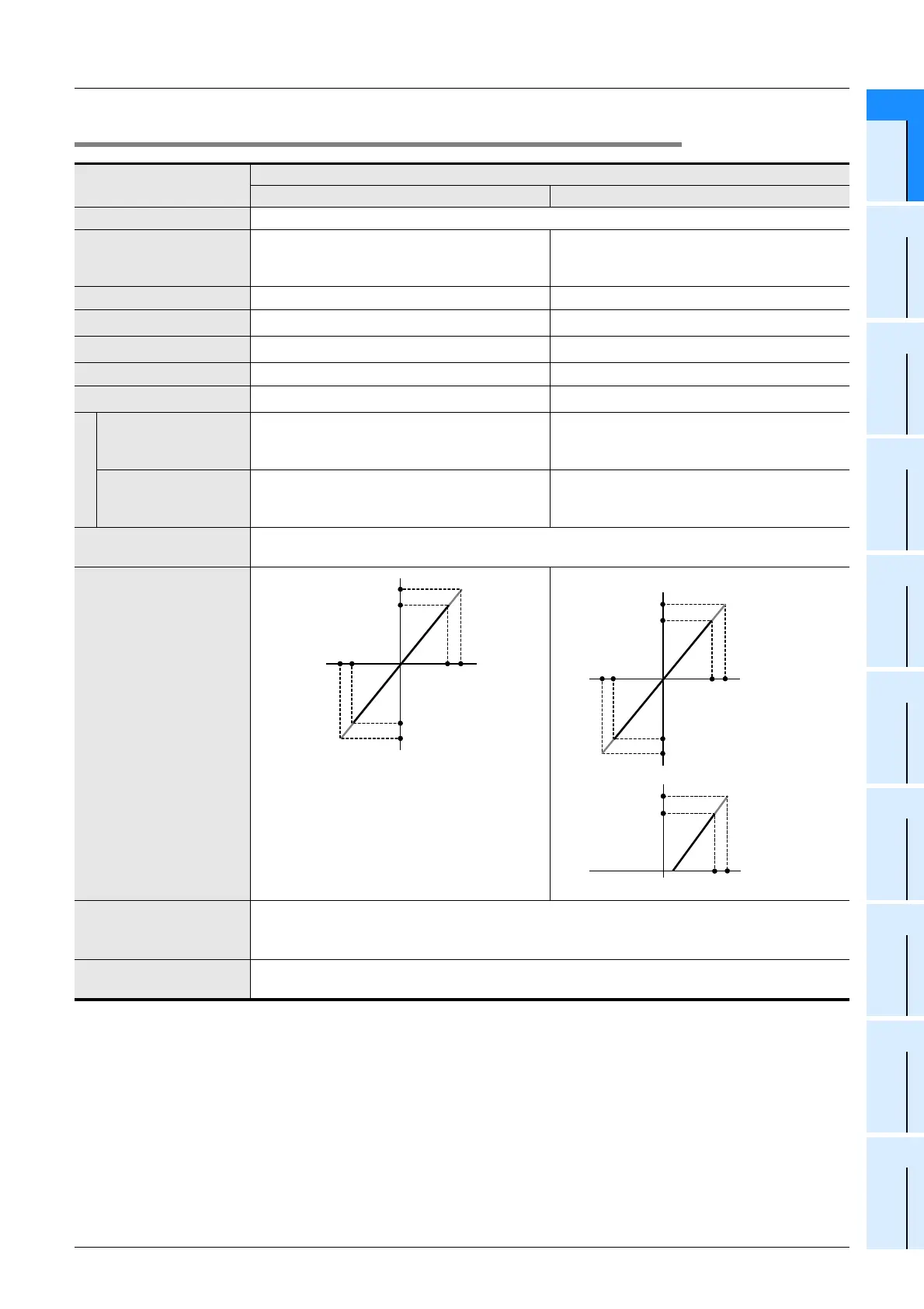
0
+2000
+10V
Approx.
+10.235V
+2047
-10V
Approx.
-10.240V
-2000
-2048
z
When the input is set to -20 mA to +20 mA:
0
+1000
+20mA
-20mA
-1000
+1600
Approx.
+32mA
-1600
Approx.
-32mA
z
When the input is set to 4 mA to 20 mA:
0
1000
20mA
4mA
1750
Approx.
32mA

 Loading...


