F-13
3 Wiring
3.4 Selection of Thermocouple
FX
3U
/FX
3UC
Series PLC User's Manual - Analog Control Edition
FX3U-4AD-TC-ADP (4-channel Thermocouple Data Input)
A
Common Items
B
FX
3UC
-4AD
C
FX
3U
-4AD-ADP
D
FX
3U
-4DA-ADP
E
FX
3U
-4AD-PT
-ADP
F
FX
3U
-4AD-TC
-ADP
G
PID Instruction
(FNC 88)
3.4 Selection of Thermocouple
3.4.1 Thermocouple type
• There are 2 types of thermocouples: type K and type J. Select the desired type. However, be sure to
connect the same type of thermocouple to all the channels.
• Be sure to use the insulation type thermocouple.
3.4.2 Compensating lead wire
To connect the thermocouple, use one of the following types of compensating lead wires:
• The compensating lead wire indicates a temperature value of approximately 0.12
°
C higher than that of the
wire resistor (10Ω). Use the compensating lead wire considering this difference.
• If the compensating lead wire is very long, the wire may be easily affected by noise, etc. It is, therefore,
recommended for the length of the compensating lead wire to be 100 m or less.
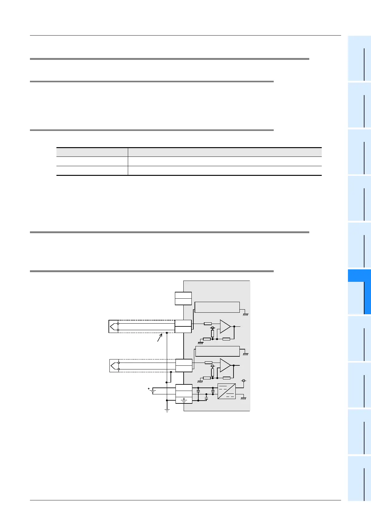
3.5 Wiring of Thermocouple
Select thermocouple type K or J. Wiring, however, depends on the selected thermocouple type. Refer to the
following wiring diagrams:
3.5.1 Wiring of thermocouple type K
*1. It is not necessary to connect lines to the J-type terminals. Leave these terminals disconnected.
*2. Keep the thermocouple away from inductive noise (commercial power, etc.).
Thermocouple Type of compensating lead wire
Type K KX,KCA,KCB,KCC
Type J JX
3k
Ω
ch
TC-ADP
Class-D
grounding
+5V
L
+
L
-
24+
24-
Compensating
lead wire
Terminal block
24V DC
L
+, L
-, ch
:
represents the channel number.
Type J
Type J
Thermocouple
type K
*2
ch
L
+
L
-
3k
Ω
Temperature
compensating circuit
Temperature
compensating circuit
Shield
OPEN*1

 Loading...


