B-40
5 Buffer Memory (BFM)
5.4 Details of Buffer Memories
FX
3U
/FX
3UC
Series PLC User's Manual - Analog Control Edition
FX3UC-4AD (4-channel Analog Input)
5.4.18 BFM #99: Clearance of upper/lower limit error data and abrupt change detection data
Initial value: H0000
Numeric data type: Hexadecimal (H)
Three error data clearance commands (lower limit error data clearance command, upper limit error data
clearance command, and abrupt change detection data clearance command) are respectively assigned to the
3 lower bits of BFM #99.
Turning on each bit (batch turning on for all the channels) will reset the corresponding error status flag (#26 or
#27 of BFM).
1. Command assignment to each bit of BFM #99
Two or more data clearance commands can be turned on at the same time.
2. Operation to be performed after resetting BFM #26, #27
Each bit will automatically be turned off.
5.4.19 BFM #101 to #104: Minimum peak value / BFM #111 to #114: Maximum peak value
Numeric data type: Decimal (K)
The minimum value of channel data (channels 1 to 4) written in BFM #10 to #13 will be written in BFM #101 to
#104 as the minimum peak value, and the maximum value of channel data will be written in BFM #111 to
#114 as the maximum peak value.
1. Caution regarding peak value
To use the minimum peak value and the maximum peak value, be sure to turn on the peak value holding
function (b3 of BFM #22).
2. Caution regarding peak value
• If the data addition function (b2 of BFM #22) is used together with this function, the addition data will be
added to the measurement data.
• If the peak holding function is not used, the peak value will be "K0".
3. Peak value automatic transfer function (b4 of BFM #22)
If the automatic transfer-to first data register is specified in BFM #125, the minimum peak value and the
maximum peak value will be automatically written in the specified data registers (8 points (registers) starting
from the first data register specified).
Only when the peak value is updated, data will be automatically transferred from 4AD to the PLC. For this
reason, the PLC does not need the program for reading data, and the scanning time of the PLC can be
shortened.
: Represents a numeric value.
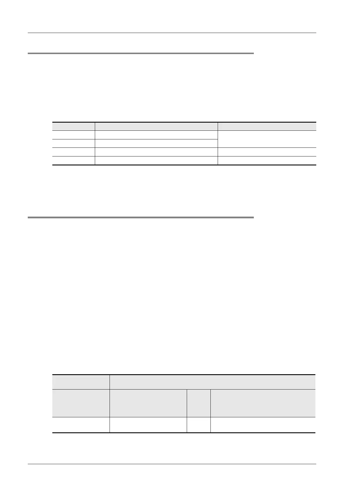
Bit No. Description Buffer memory to be cleared
b0 Lower limit error data clearance command
BFM #26
b1 Upper limit error data clearance command
b2 Abrupt change detection data clearance command BFM #27
b3 to b15 Not used. -
Convenient function
setting
Automatic data transfer function
ON = Valid Transfer-from buffer memory
Transfer-to data register specification
(BFM #128: K
)
(8 points (registers) starting from the
specified data register)
BFM #22 b4:ON
BFM #22 b3:ON
BFM #101 to 104
BFM #111 to 114
→
D
to D+3
D
+4 to D+7

 Loading...


