G-6
2 How to Use PID Instruction
FX
3U
/FX
3UC
Series PLC User's Manual - Analog Control Edition
PID Instruction (FNC 88)
2.2 Relationship Between Parameter Setting and Auto Tuning
Explanation of set items
*1. When auto tuning is not executed, the same number of devices as those occupied in the step
response method become occupied.
2.2 Relationship Between Parameter Setting and Auto Tuning
1. When auto tuning is not executed (parameter setting)
It is necessary to write the set value of the parameters to +6 using MOV instruction in advance,
etc. before starting the PID operation when auto tuning is not executed.
If data registers in the latch area backed up against power failure are specified, the setting data is held even
after the power of the PLC is turned OFF. Accordingly, writing is not necessary when the power is turned ON
at the second time or later.
2. When auto tuning is executed
The proportional gain ( +3), integral time ( +4) and differential time ( +6) are important
constants for executing the auto tuning function described later and for optimizing the PID control. These
constants can be set automatically.
→ For a detailed description of auto-tuning (limit cycle method), refer to Section. 4.1.
→ For a detailed description of auto-tuning (step response method), refer to Section. 4.2.
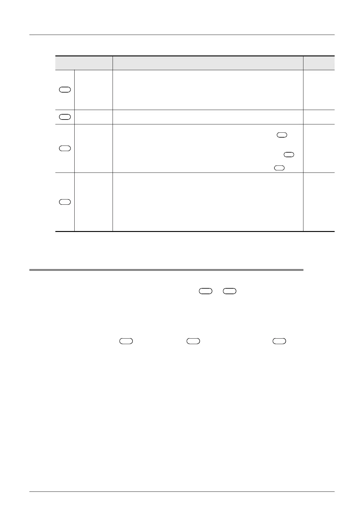
Set item Description
Occupied
points
Target value
(SV)
• The target value (SV) is set.
• PID instruction does not change the settings.
• Caution on using the auto tuning (limit cycle method)
If the target value for auto tuning is different from the target value in the PID
control, it is necessary to set a value to which a bias value is added, and then
store the actual target value when the auto tuning flag turns OFF.
1
Measured
value (PV)
This is the input value of the PID operation. 1
Parameter
*1
1) Auto tuning (in the limit cycle)
Twenty-nine devices are occupied from the head device specified in .
2) Auto tuning (in the step response method)
a) Operation setting (ACT): When bits 1, 2 and 15 are something other than "0"
Twenty-five devices are occupied from the head device specified in .
b) Operation setting (ACT): When bits 1, 2 and 15 are "0"
Twenty devices are occupied from the head device specified in .
29
25
20
Output value
(MV)
1) PID control (normal processing)
The user sets the initial output value before driving the instruction.
After that, the operation result is stored.
2) Auto tuning (in the limit cycle method)
The ULV or LLV value is automatically output during auto tuning. The specified
MV value is output when auto tuning is finished.
3) Auto tuning (in the step response method)
The user sets the step output value before driving the instruction.
The MV value is not changed by PID instruction during auto tuning.
1
S
1
S
2
S
3
S
3
S
3
S
3
D
S
3
S
3
S
3
S
3
S
3
S
3
S
3
S
3
S
3

 Loading...


