G-8
3 Parameter
FX
3U
/FX
3UC
Series PLC User's Manual - Analog Control Edition
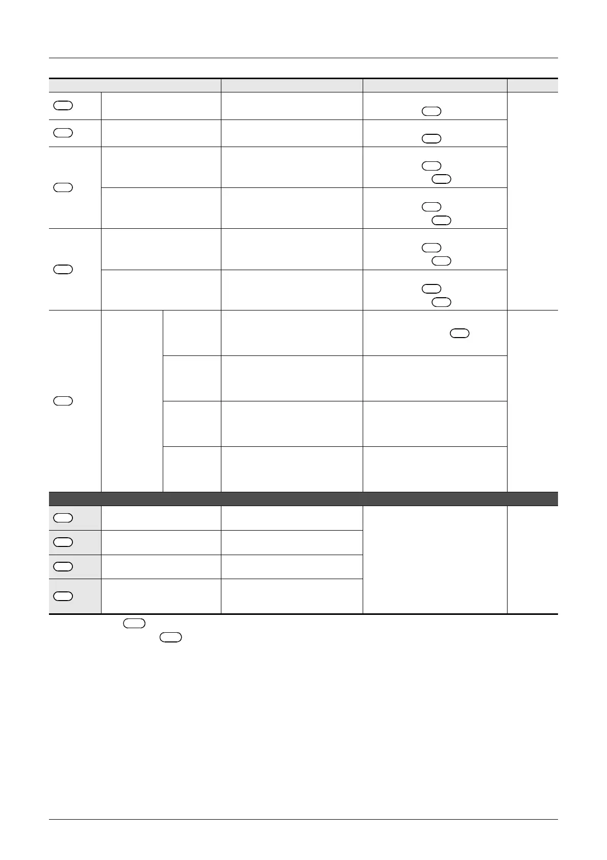
PID Instruction (FNC 88)
3.1 Parameter List: (S3) to (S3) + 28
*1. +20 through +24 become occupied only if bits 1, 2, or 5 are set to "1" to determine the action
(ACT) of +1.
+20
*1
Input variation (incremental)
alarm set value
0 to 32767
It is valid when operation direction
(ACT) (bit 1 of +1) is "1".
Subsection
3.2.2
+21
*1
Input variation (decremental)
alarm set value
0 to 32767
It is valid when operation direction
(ACT) (bit 1 of +1) is "1".
+22
*1
Output variation
(incremental) alarm set value
0 to 32767
It is valid when operation direction
(ACT) (bit 2 of +1) is "1"
or (ACT) (bit 5 of +1) is "0".
Output upper limit set value −32768 to 32767
It is valid when operation direction
(ACT) (bit 2 of +1) is "0"
or (ACT) (bit 5 of +1) is "1"
+23
*1
Output variation
(decremental) alarm set value
0 to 32767
It is valid when operation direction
(ACT) (bit 2 of +1) is "1"
or (ACT) (bit 5 of +1) is "0"
Output lower limit set value −32768 to 32767
It is valid when operation direction
(ACT) (bit 2 of +1) is "0"
or (ACT) (bit 5 of +1) is "1"
+24
*1
Alarm output
bit0
0: Input variation (incremental) is not
exceeded.
1: Input variation (incremental) is
exceeded.
It is valid when operation direction
(ACT) (bit 1 or bit 2 of +1) is
"1".
Subsection
3.2.8
bit1
0: Input variation (decremental) is
not exceeded.
1: Input variation (decremental) is
exceeded.
bit2
0: Output variation (incremental) is
not exceeded.
1: Output variation (incremental) is
exceeded.
bit3
0: Output variation (decremental) is
not exceeded.
1: Output variation (decremental) is
exceeded.
The setting below is required when the limit cycle method is used (when the operation direction (ACT) b6 is set to ON).
+25
PV value threshold
(hysteresis) width (SH
PV)
Set it according to measured value
(PV) fluctuation.
They are occupied when operation
direction (ACT) (bit 6) is "ON (limit
cycle method)."
Chapter 4
+26
Output value upper limit
(ULV)
Set maximum value (ULV) of output
value (MV).
+27
Output value lower limit
(LLV)
Set minimum value (LLV) of output
value (MV).
+28
Wait setting from end of tuning
cycle to start of PID control
(K
W)
−50 to 32717%
Set item Setting Remarks Reference
S
3
S
3
S
3
S
3
S
3
S
3
S
3
S
3
S
3
S
3
S
3
S
3
S
3
S
3
S
3
S
3
S
3
S
3
S
3
S
3
S
3
S
3
S
3
S
3
S
3
S
3
S
3
S
3
S
3
S
3
S
3

 Loading...


