App-142
TableApp.2.1 Device Comparison
*1 : The number of device points can be changed at the parameters.
*2 : CPU uses V as an edge relay.
*3 : Instructions that used accumulators with the AnNCPU, AnACPU, and AnUCPU have different formats with
the QCPU.
*4 : Can only be used by the $MOV instruction with the Q00JCPU, Q00CPU, and Q01CPU.
*5 : The Q00JCPU does not have file registers.
*6 : Applicable to products with the first 5 digits of the serial number 04122 or higher
(Q00JCPU, Q00CPU, and QCPU).
*7 : Each 5 points of FX0 to FX4 and FY0 to FY4 can be used on the programs.
*8 : The number of points that can be used on the programs
*9 : The number of accessible points to actual I/O modules
*10 : The Q00UJCPU does not have file registers.
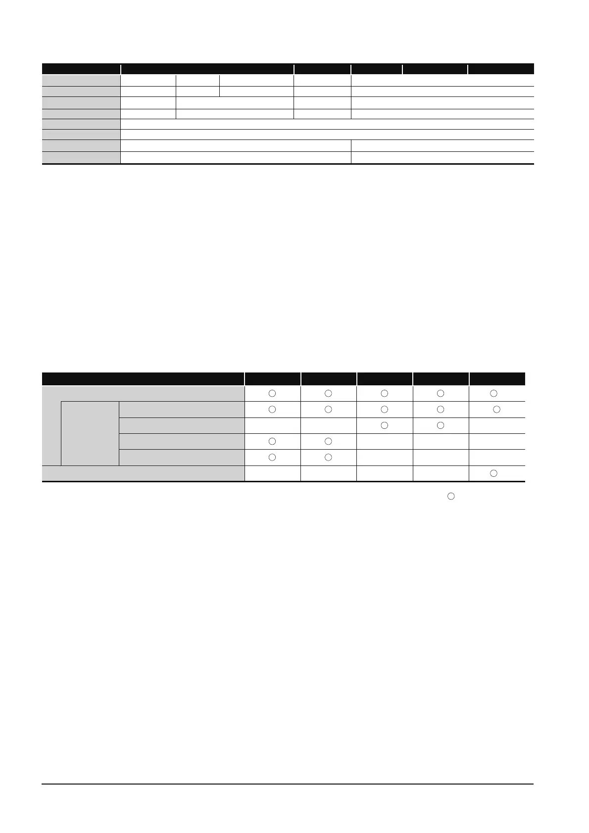
Appendix 2.1.2 I/O control mode
TableApp.2.2 I/O Control Mode
Symbol in table : Usable, ––: Unusable
*1 : The DOUT, DSET, and SRST instructions are direct output dedicated instructions.
There are no dedicated instructions for direct input.
*2 : Switching between the refresh mode and direct mode is conducted with an AnNCPU DIP switch.
Device name QCPU LCPU AnUCPU AnACPU AnNCPU
Pointer
300 points 512 points
4096 points
4096 points 256 points
Interrupt pointers
128 points 128 points 256 points 256 points 32 points
SFC blocks
126
*6
320 points 320 points
––
SFC transition devices
––
512 points 512 points
––
Decimal constants
K - 2147483648 toK2147483647
Hexadecimal constants
H0 to HFFFFFFFF
Real number constants
*
6
E ± 1.17550-38 to E ± 3.40282+38
––
Character string
"QnACPU", "ABCD"
*4
––
I/O control mode QCPU LCPU AnUCPU AnACPU AnNCPU
Refresh mode
*2
Direct
I/O method
Partial refresh instructions
Dedicated instruction
*1
–– –– ––
Direct access input
–– –– ––
Direct access output
–– –– ––
Direct mode
–– –– –– ––
*2

 Loading...


