110
OPERATING PROCEDURE
PHOTOS & ILLUSTRATION
4.
Removing the thermistors <Low pressure saturated
temp.>
(TH6) and <Outdoor> (TH7)
Remove
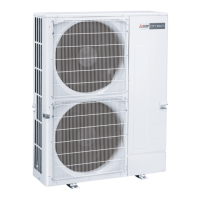
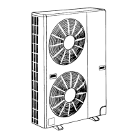
(1) Remove the top panel and the service panel. (See Photo 1)
(2) Disconnect the connector that TH6 and TH7 share on the
multi controller board in the electrical parts box.
(3) Remove the thermistor <Low pressure saturated temp.>
(TH6) from the sensor holder. (See Photo 6)
(4) Unfasten clamps to remove the TH6 lead wire.
(5) Remove the thermistor <Outdoor> (TH7) from the sensor
holder. (See Photo 7)
(6) Loosen clamps on top of the electrical parts box. (See
Photo 8)
Note:
TH6 and TH7 cannot be replaced individually as they
share a connector. To replace TH6 or TH7, remove
both of the thermistors.
Photo 7
Lead wire of thermistor
<Outdoor> (TH7)
Sensor holder
(5) Remove the terminal cover and disconnect the compres-
sor lead wire.
(6) Remove the thermistor (TH7) from the sensor holder.
(7) Remove electrical parts box fixing screws (4 × 10) and
remove the electrical parts box by lifting it. The electrical
parts box is fixed with 2 hooks on the left and 1 hook on
the right. (See Photo 5)
Photo 5
Electrical
parts box
Photo 8
Clamps
Electrical
parts box
Multi controller
board (MULTI.B)
Electrical parts
box fixing screws
TH7 lead wire
<Top view of outdoor unit with top panel removed>
Heat
exchanger
Photo 6
<Back view of outdoor unit >
Front
Back
Thermistor
<Low pressure
saturated temp.>
(TH6)
 Loading...
