EasyManua.ls Logo

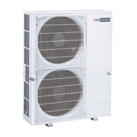
Mitsubishi PUMY-P60NKMU - Refrigerant System Diagram

Mitsubishi PUMY-P60NKMU
114 pages
To Next Page IconTo Next Page
To Previous Page IconTo Previous Page
Loading...
20
7-2. REFRIGERANT SYSTEM DIAGRAM
PUMY-P60NKMU
PUMY-P60NKMU-BS
Refrigerant
Gas pipe
<3/4>
Refrigerant
Liquid pipe
<3/8>
Accumulator
Thermistor (TH6)
(Saturation temperature
of suction pressure)
Solenoid
valve (SV1)
Check valve
(High pressure)
Check valve
(Low pressure)
High pressure
sensor (63HS)
High pressure
switch (63H)
Low pressure
sensor (63LS)
Thermistor (TH7)
(Outdoor temperature)
(Pipe temperature)
Thermistor (TH4)
Thermistor (TH3)
Oil separator
Service port
Service
port
4-way valve
Strainer
Strainer
Capillary
tube
Strainer
Strainer
Ball valve
Stop valve
Distributor
Strainer Strainer
Compressor
Strainer
Refrigerant piping specifications <dimensions of flared connector>
Capillary tube for oil separator : :2.5 % :0.8 % L800
Capillary tube for solenoid valve : :4.0 % :3.0 % L500
Capacity
Item
Liquid piping
Gas piping
P06, P08, P12, P15, P18
P24, P30, P36, P48, P54
P60
Indoor unit
Outdoor unit
:6.35 <1/4>
:9.52 <3/8>
:9.52 <3/8>
:12.7 <1/2>
:15.88 <5/8>
:19.05 <3/4>
P72 :9.52 <3/8> :19.05 <3/4>
Thermistor (TH2)
(HIC)
(
Compressor
)
HIC
LEV-B
LEV-A
Unit: mm <inch>
OCH502C

Table of Contents

Related product manuals