5 - 3 5 - 3
MELSEC-Q
5 DATA COMMUNICATION USING THE MELSEC COMMUNICATION
PROTOCOL
(2) System settings using the GX Configurator-SC
When it is necessary to change the default values registered in the Q series C24,
perform the settings as indicated in Chapter 8 and register these to the flash
ROM in the Q series C24.
• MC protocol system setting
• Transmission control and others system setting
POINT
To write from the external device to the intelligent function module installed in the
MELSECNET/H remote I/O station during communication using the MC protocol,
set the "Write allow/prohibit during PLC CPU RUN" in the GX Developer to enable.
5.1.4 Support of multiple CPU system or redundant system
When the external device accesses a QCPU in a multiple CPU system or redundant
system, it is possible to selectively access either a control or non-control CPU in the
multiple CPU system or a control or standby system CPU or System A or System B
CPU in the redundant system by specifying the target QCPU in "Requested module
I/O No." of the QnA compatible 4C frame for the MC protocol.
Refer to the Reference Manual for details.
Refer to Chapter 2 of this manual for the system configuration.
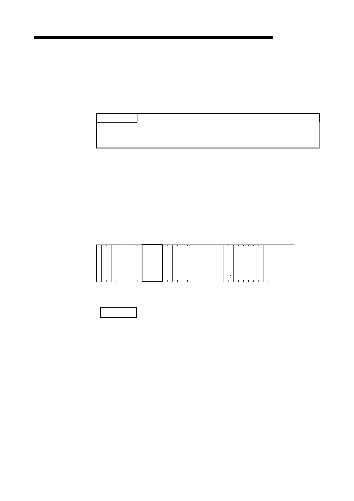
(Example) When multiple CPU No.1 is specified
Frame ID No.
46
H
05
H
Self-station No.
Command
Sub command
Device code
Head device
Number of device
points
Sum check code
38
H
30
H
33
H
30
H
33
H
45
H
30
H
30
H
30
H
30
H
30
H
30
H
34
H
30
H
31
H
30
H
30
H
30
H
31
H
58
H
2A
H
30
H
30
H
30
H
30
H
34
H
30
H
30
H
30
H
30
H
35
H
H
F
L
8
H
0
L
7
H
0
L
0
H
0
L
0
H
0
L
0
H
0
L
1
H
0
L
1
X
L
0
L
5
PC No.
—
0
—
0
H
0
—
0
—
4
H
0
—
0
—
0
—
4
—
3
—
0
—
0
—
0
E
N
Q
Station No.
30
H
35
H
H
0
L
5
Network No.
30
H
37
H
H
0
L
7
—
E
33
H
36
H
H
3
L
6
Requested module
station No.
Requested module
I/O No.
(Command massage of the QnA compatible 4C frame format 1)
REMARK
• When using the Q series C24 in a multiple CPU system, it is necessary to specify
the QCPU that controls the Q series C24 (hereinafter referred to as the control
PLC) using GX Developer.
• It is also possible to mount a Q series C24 of function version A in a multiple CPU
system. In this case, it is only possible to access the control PLC (PLC No.1).
• It is only possible to access the control PLC if data is communicated by means of
frames other than the QnA compatible 4C frame.

 Loading...


