4 - 1 4 - 1
MELSEC-Q
4 SETTINGS AND PROCEDURES PRIOR TO OPERATION
4
4 SETTINGS AND PROCEDURES PRIOR TO OPERATION
This chapter explains the settings and procedures required before starting a system
that uses the Q series C24.
POINT
(1) When using the Q series C24, please read the safety precautions at the
beginning of this manual.
(2) The installation and setup methods of the Q series C24 are the same as those
for CPU modules.
(3) For module installation and setup, see the user's manual for the PLC CPU
used.
4.1 Handling Precautions
The following explains the precautions for handling the Q series C24:
(1) Do not drop the module or subject it to heavy impact since it is made of resin.
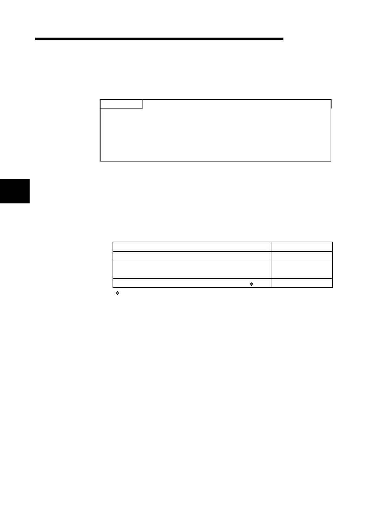
(2) Tighten the module terminal and fixing screws within the specified tightening
torque range as follows:
Screw location Tightening torque range
RS-422/485 terminal block terminal screws (M3 screw) 0.42 to 0.58 N · m
RS-422/485 plug-in connector socket terminal screw for
QJ71C24N-R4 (M2 screw)
0.20 to 0.25 N · m
Module fixing screw (normally not required) (M3 screw) ( 1) 0.36 to 0.48 N · m
1 A module can be easily fixed to a base unit using the hooks in the upper part
of the module. However, it is recommended that the module be fixed using
the module mounting screws when it is used in a place subject to vibration or
impact.
 Loading...


