6 - 6 6 - 6
MELSEC-Q
6 DATA COMMUNICATION USING THE NON PROCEDURE PROTOCOL
6.1.2 The receive area and the received data list
The following shows the list of the receive area and the receive data for performing
data reception using the non procedure protocol.
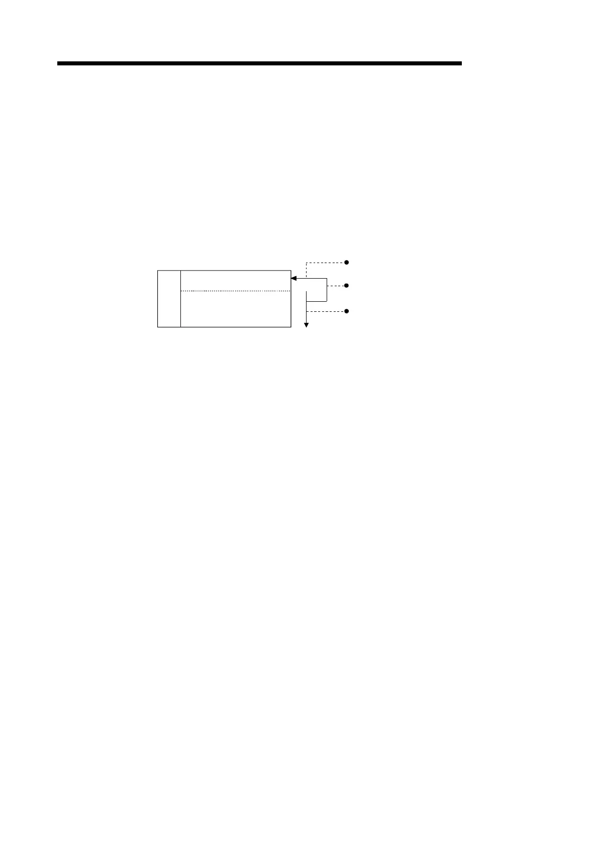
(1) Receive area
The receive area is a memory area for storing the data received from the external
device and the receive data count in order to read the receive data for the PLC
CPU. By default, the receive area is assigned to addresses 600
H
to 7FF
H
(CH1
side) and A00
H
to BFF
H
(CH2 side).
Buffer memory
Receive data count storage area
Receive data storage area
CH1
address
600
H
601
H
7FF
H
(Default)
Writes the receive data storage count when the PLC CPU
is requested to read the receive data.
Stores the arbitrary data area of the receive data.
The receive data count units (word/byte) are up to the value
set to GX Configurator-SC word/byte units designation.
Receive area
•
•
•
to

 Loading...


