6 - 19 6 - 19
MELSEC-Q
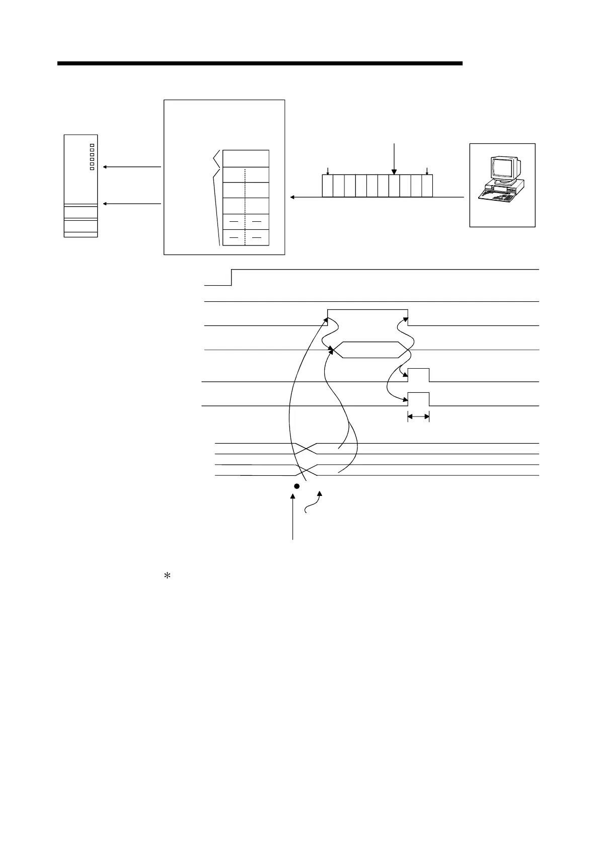
6 DATA COMMUNICATION USING THE NON PROCEDURE PROTOCOL
Reception
abnormal
detection
Receive area
(buffer memory)
Receive data
count storage
area
STX
D
(02
H
)
(44
H
)
B
(42
H
)
(03
H
)
A
(41
H
)
E
(45
H
)
C
(43
H
)
(00
H
)
STX A BCDEFGHETX
Head data
Receive
complete code
(02
H
)(41
H
)(48
H
)(47
H
)(46
H
)(45
H
)(44
H
)(43
H
)(42
H
)(03
H
)
Transmission data
External device
Reception error causing data
PLC CPU
RUN.
ERR.
USER.
BAT.
BOOT.
RS-232
USB
Q25HCPU
MODE.
3
Q series C24
INPUT
instruction
Receive data
storage area
Q series C24 ready signal
Reception data read request
Reception abnormal
detection signal
INPUT instruction
INPUT instruction complete device
INPUT instruction complete device + 1
(normal completion/abnormal
completion)
Receive data count storage area
(Buffer memory address: 600
H
)
Receive data storage area
(Buffer memory addresses: 601
H
to)
INPUT
(X1E)
(X3)
(X4)
Receive data
Data reception
1 scan
ERR LED lights up
Reception abnormal
detection data
n
3
When the data from "G" to in the reception message shown in the figure above is
received normally, the data is stored in the Q series C24 OS area.
The receive data stored in the OS area will be read to the PLC CPU in the
succeeding read operation.
 Loading...


