3 - 9 3 - 9
MELSEC-Q
3 SPECIFICATIONS
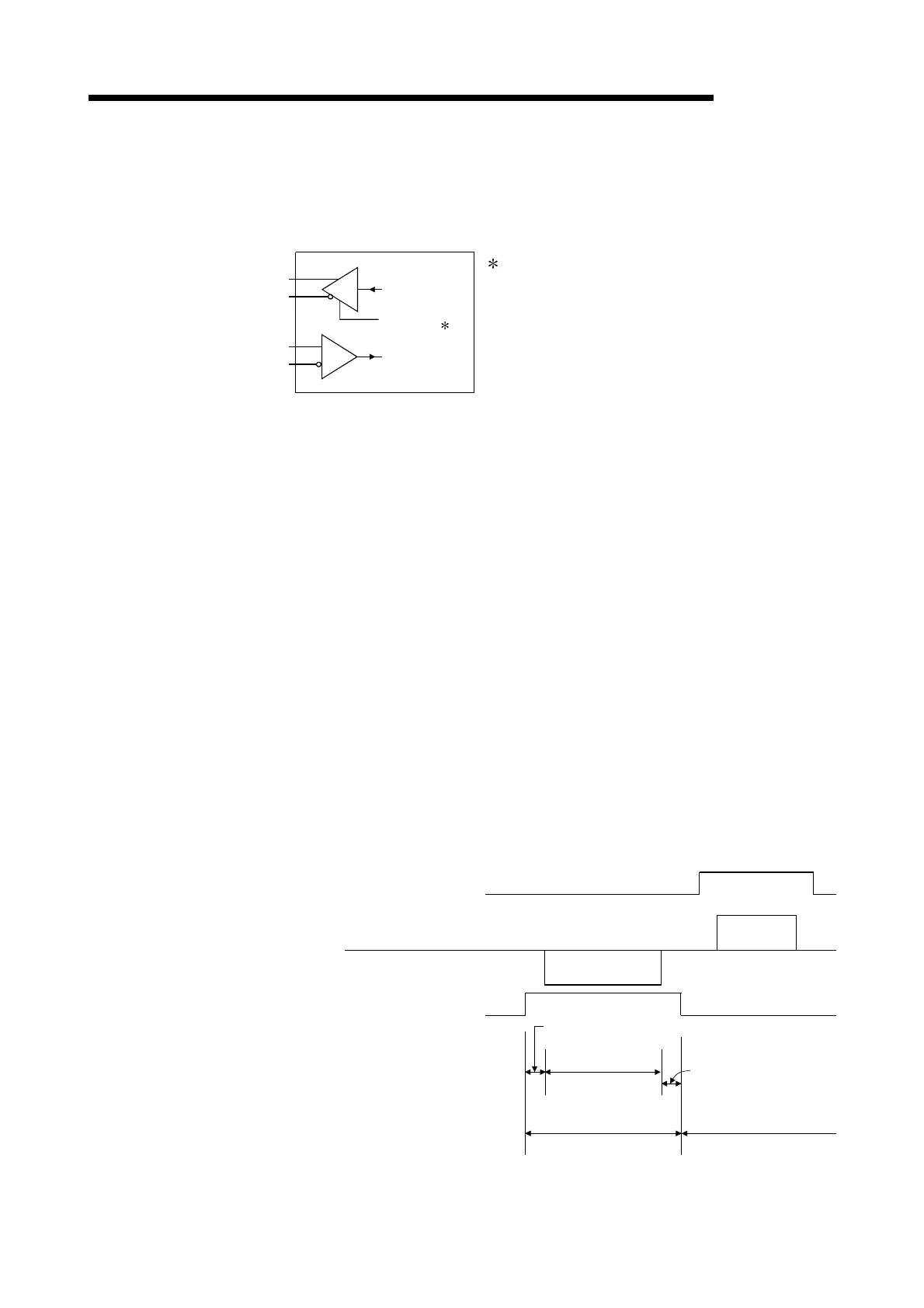
(2) RS-422/485 interface operation
1) RS-422-485 interface construction
The following illustration shows the construction of the Q series C24 RS-
422/485 interface driver (send)/receiver (receive).
Receive data
Send data
SDR
SDB
RDA
RDB
Output control input ( 1)
Receiver
Driver
1 "Output control input" (also called send gate) of
the driver (send) section of the illustration at
the left determines whether or not data from
SDA/SDB is output to the outside.
2) RS-422/485 interface operation
When the "Output control input" in the illustration above is ON, the interface
enters the low impedance state (state in which data can be sent).
When the "Output control input" is OFF, the interface enters the high
impedance state (state in which data cannot be sent).
3) Timing to start sending and to complete the transmission processing for the Q
series C24
• Timing to start sending
During data transmission, the Q series C24 outputs the actual data after
sending a mark for 2 characters, or longer, after the high impedance set by
the operations described in 1) and 2) above is reset.
• Transmission processing completion timing
The following times are necessary as H/W gate OFF time from the time that
data transmission is completed until transmission processing is completed
(the state changes to the high impedance state). (The transmission rate set
in the Q Series C24 is the object.)
When the transmission rate
is 600 bps or higher
: Time for 0 to 1 bits of data to be sent
When the transmission rate
is 50 bps, 300 bps : several ms
Outputs a mark for 2 characters, or longer
Data send time range
H/W gate OFF time
(See explanation above)
Q series C24 is in the data
transmission and data
reception enable status
(Output control input)
External device
Q series C24
Data
Data
(Output control input)
"Output control input"
ON time range
(Low impedance state)
"Output control input"
OFF time range
(High impedance state)
Q series C24 is in the data
reception enable state.
 Loading...


