4 - 4 4 - 4
MELSEC-Q
4 I/O COMBINED MODULE
4.2 QX41Y41P I/O Combined Module
• When using the module, configure the system according to Section 1.2.3 (2).
• The module uses sequential I/O numbers for input and output.
For I/O numbers of I/O combined modules, refer to Section 1.2.3.
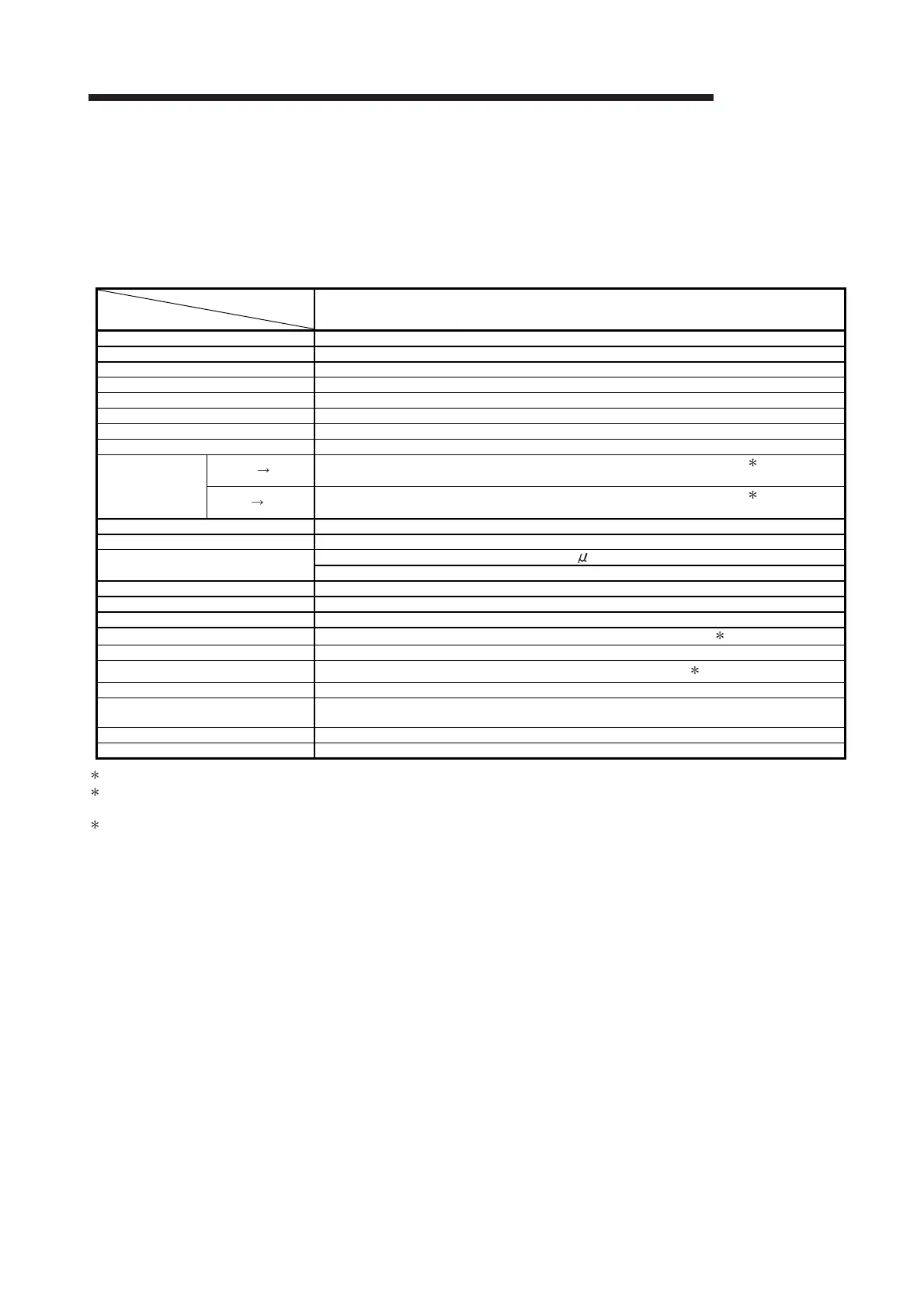
(1) DC input specifications (positive common type)
Type
Specifications
QX41Y41P I/O combined module (input specifications)
Number of input points 32 points
Isolation method Photocoupler
Rated input voltage 20.4 to 28.8VDC (ripple ratio within 5%)
Rated input current Approx. 4mA
Input derating See the derating chart.
ON voltage/ON current 19V or higher/3mA or higher
OFF voltage/OFF current 11V or lower/1.7mA or lower
Input resistance Approx. 5.6kΩ
Response time
OFF ON
1ms/5ms/10ms/20ms/70ms or less (configured in PLC parameter) 1
(Default: 10ms)
ON OFF
1ms/5ms/10ms/20ms/70ms or less (configured in PLC parameter) 1
(Default: 10ms)
Dielectric withstand voltage 560VAC rms/3 cycles (altitude 2000m)
Insulation resistance 10MΩ or more by insulation resistance tester
Noise immunity
By noise simulator of 500Vp-p noise voltage, 1 s noise width and 25 to 60Hz noise frequency
First transient noise IEC61000-4-4: 1kV
Protection degree IP2X
Common terminal arrangement 32 points/common (common terminal: 1B01, 1B02)
Number of occupied I/O points 64 points (I/O assignment is set as a 64-point I/O combined module.)
Operation indicator
ON indication (LED), 32-point switchover using switch 2
External connections 40-pin connector
Applicable wire size
0.088 to 0.3mm
2
(For A6CON1 or A6CON4) 3
Applicable connector A6CON1, A6CON2, A6CON3, A6CON4 (optional)
Applicable connector/terminal block
converter module
A6TBXY36, A6TBXY54, A6TBX70
Internal current consumption (5VDC) 130mA (TYP, all points ON)
Weight 0.20kg
1: For the setting method, refer to the Section 1.3.1.
2: Selection of left-hand (F) side provides the first half (X00 to X1F) LED indications, and selection of right-hand (L) side provides the
latter half (Y20 to Y3F) LED indications.
3
: When using A6CON2 or A6CON3, refer to Chapter 7.

 Loading...