2 - 34 2 - 34
MELSEC-Q
2 INPUT MODULE SPECIFICATIONS
2.25 QX90H DC High-speed Input Module (Negative Common Type)
Type
Specifications
DC high-speed input module (Negative common type)
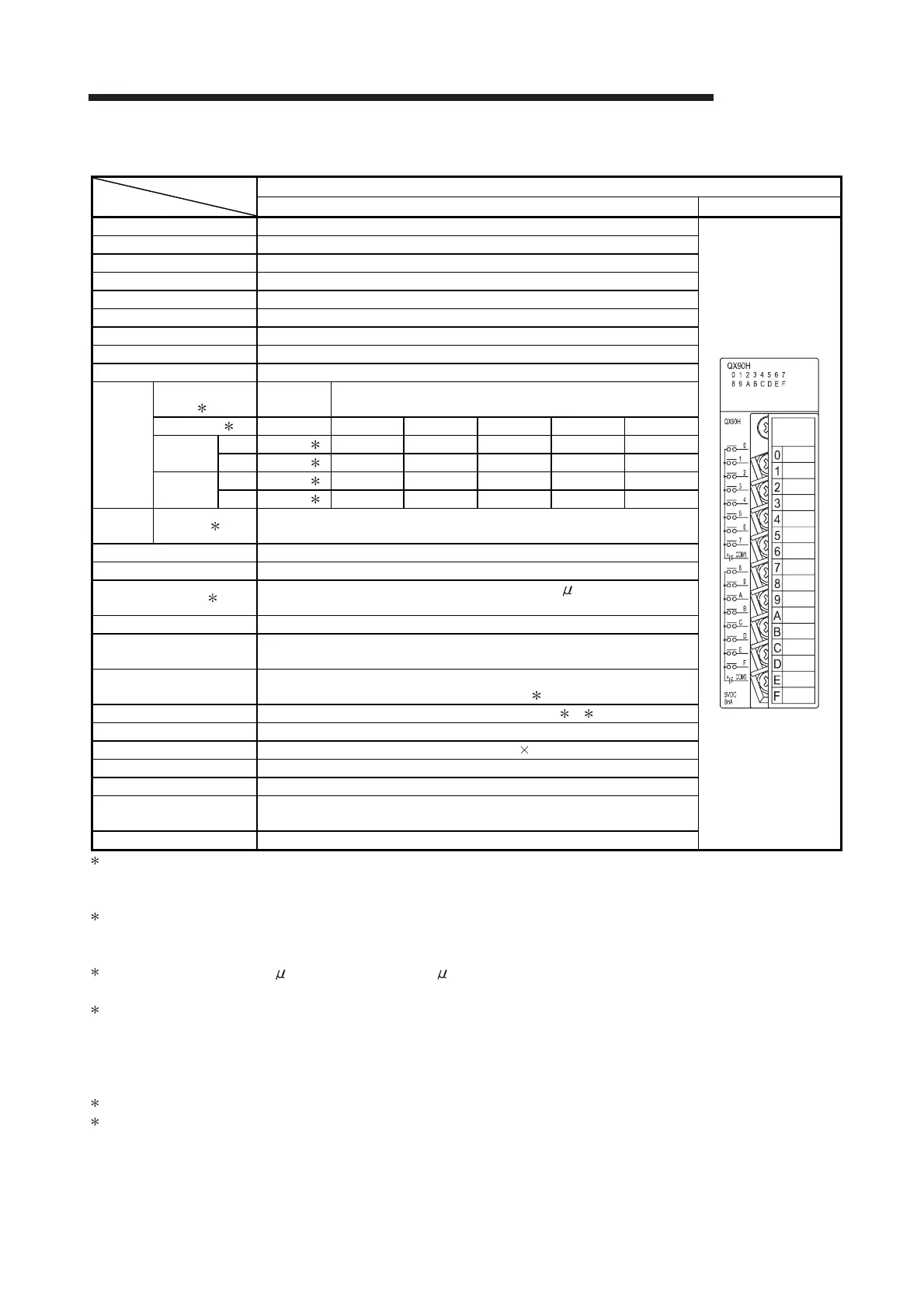
QX90H Appearance
Number of input points 16 points
Isolation method Photocoupler
Rated input voltage 5VDC (+20/-15%, ripple ratio within 5%)
Rated input current Approx. 6mA
Input derating None
ON voltage/ON current 3.5V or higher/3mA or higher
OFF voltage/OFF current 1V or lower/1mA or lower
Input impedance Approx. 470Ω
Response
time
SW1 (noise filter)
1
OFF ON
Set value 2 Invalid 0.1 0.2 0.4 0.6 1
OFF to ON
TYP. 0ms 3 0.04ms 0.10ms 0.25ms 0.50ms 0.95ms
MAX. - 3 0.05ms 0.15ms 0.30ms 0.60ms 1.00ms
ON to OFF
TYP. 0ms 3 0.04ms 0.10ms 0.25ms 0.50ms 0.95ms
MAX. - 3 0.05ms 0.15ms 0.30ms 0.60ms 1.00ms
Function
setting
SW2 4 OFF: Interrupt, ON: High-speed input
Dielectric withstand voltage 560VAC rms/3 cycles (altitude 2000m)
Insulation resistance 10MΩ or more by insulation resistance tester
Noise immunity 5
By noise simulator of 500Vp-p noise voltage, 1 s noise width
and 25 to 60Hz noise frequency
Protection degree IP2X
Common terminal
arrangement
8 points/common (common terminal: TB9, TB18)
Number of occupied I/O
points
16 points (I/O assignment is set as a 16-point high-speed input module or 16-
point interrupt module.) 4
Interrupt processing condition Set by Switch setting in GX Developer 4 6
Operation indicator ON indication (LED)
External connections 18-point terminal block (M3 6 screws)
Applicable wire size 0.3 to 0.75mm
2
core (2.8mm OD max.)
Applicable crimping terminal R1.25-3 (Sleeved crimping terminals cannot be used.)
Internal current consumption
(5VDC)
80mA (TYP. all points ON)
Weight 0.14kg
1
: If the noise filter selector switch (switch 1) on the bottom of the module (refer to Chapter 10) is turned on, the noise filter takes effect.
The off-status noise filter disables I/O response time setting.
After switching on or off the switch 1, reset the power supply of the CPU module.
2: Set an input response time in
"
I/O response time
"
combo box of PLC parameter in GX Developer. (Default: 0.2ms)
A response time setting value can be changed in GX Developer (SW6D5C-GPPW or later).
For the setting details, refer to Section 1.3.1.
3: The actual response time is 5 s delay when turning on, 10 s delay when turning off, because the hardware response time is added.
For the details of the CPU overhead time, refer to manuals for the CPU module used (Function Explanation, Program Fundamentals).
4: The module function can be changed according to the status of the function selector switch (switch 2) on the bottom of the module
(refer to Chapter 10).
ON: High-speed input
OFF: Interrupt
If the function selector switch (switch 2) setting is changed while the CPU module is in RUN, an error (error code: 2100) occurs.
5: Indicates the noise immunity when the noise filter takes effect (the noise filter selector switch (switch 1) is turned on).
6: For the setting method, refer to Section 1.3.3.

 Loading...