11 - 2 11 - 2
MELSEC-Q
11 I/O MODULE TROUBLESHOOTING
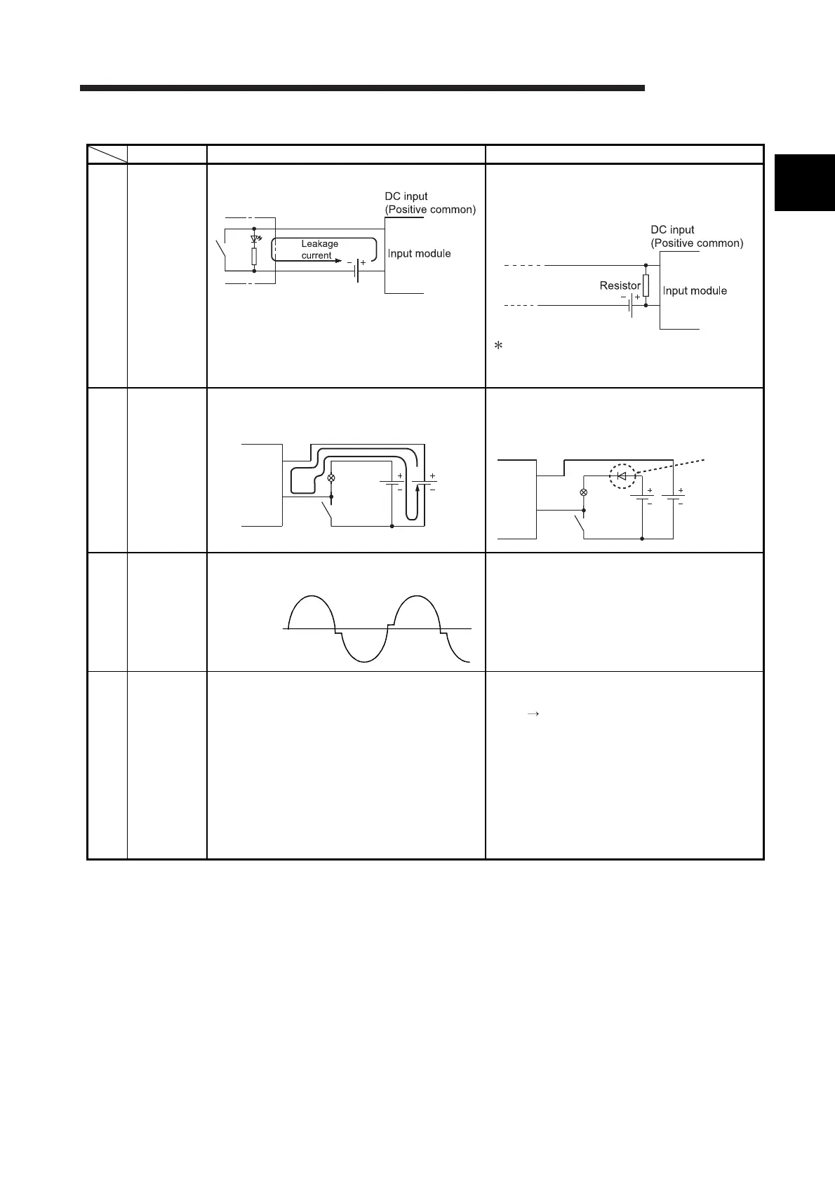
Table 11.1 Input Circuit Problems and Corrective Actions (Continued)
Condition Cause Corrective action
Example 4
An input
signal does
not turn off.
• Drive by switch with LED indicator.
Connect an appropriate resistor so that the
current flow within the module will be less than
the off current.
A calculation example of a value for a
connected resistor is given on the following
page.
Example 5
An input
signal does
not turn off.
• Current flow in the opposite direction due to
the use of two power supplies
• Use only one power supply.
• Connect a diode so that current flows only in
one direction. (Figure below)
Example 6
An input
signal does
not turn on
(AC input
module).
Stepwise distortion as shown below appears to
the zero cross voltage of input signal (AC).
Improve input signal waveform by using the
uninterruptible power system etc.
Example 7
False input
due to
noise
Noise has been taken as input data. Change the response time setting value.
*1
Example
1ms 5ms
If this action is not effective, take the following
measures.
• To prevent excessive noise, avoid installing
power cables together with I/O cables.
• Take noise reduction measures. (Example:
Connect surge absorbers to noise-generating
devices such as relays and contactors using
the same power supply.)
*1: If excessive noise is periodically generated, setting a shorter response time value may be effective.
E1E2
Input
module
DC input
E1>E2
Lamp
Diode
E1
Lamp
E2
DC input
Input
module
Zero cross
voltage
11

 Loading...