11 - 6 11 - 6
MELSEC-Q
11 I/O MODULE TROUBLESHOOTING
Table 11.2 Output Circuit Problems and Corrective Actions (Continued)
Condition Cause Corrective action
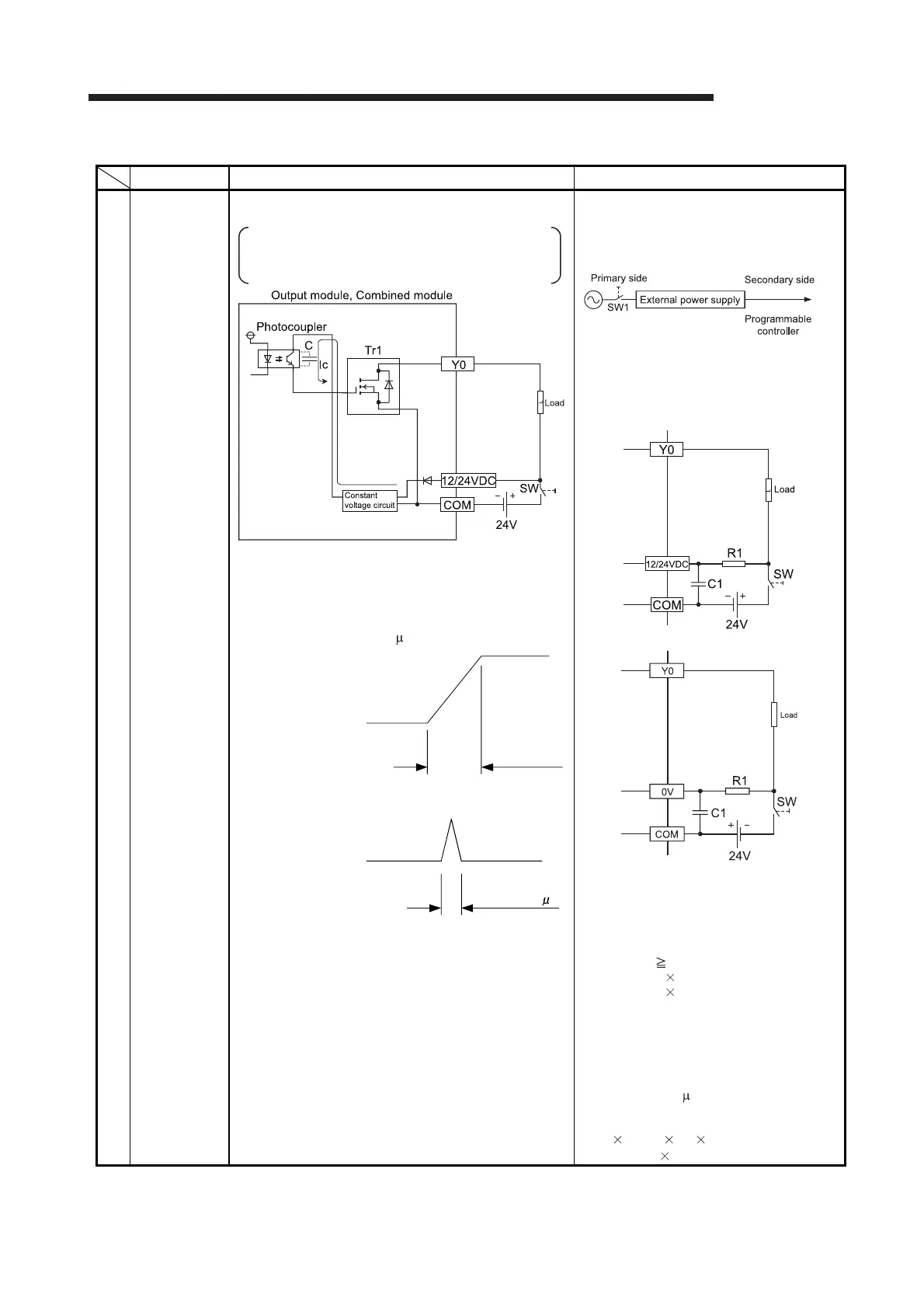
Example 4
When the
external power
supply turns
on, the load
turns on for a
moment.
(transistor
output)
Erroneous output due to the stray capacitance (C) between
collector and emitter of photocoupler.
There is no erroneous output at normal load.
An erroneous output may occur at high sensitivity load
(such as solid state relay)
(1) If the external power supply is turned on precipitously, Ic
current flows due to the stray capacitance (C) between
collector and emitter of photocoupler.
(2) Ic current flows to the next stage of transistor Tr1 gate and
Y0 output turns on by 100 s.
(1) To turn on or off the external power supply,
check that the external power supply rising
edge must be 10ms or more, and switch the
SW1 to the primary side of external power
supply.
(2) When switching to the secondary side of the
external power supply is required, the
external power supply rising edge
connected a condenser and a resistor must
be slow, and measured 10ms or more.
Sink output
Source output
* The measures are ineffective in the following
modules due to the characteristic of the external
power supply circuit
QY81P
QY82P
R1: Several tens of ohms
Power capacity
(external power supply current
*1
)
2
resistance value
(3 to 5)
*2
C1: several hundreds of microfarads 50V
*1 Refer to current consumption of the external power
supply for modules used in this manual.
*2 Select the power capacity of resistance to be 3 to 5
times larger than the actual power consumption.
(Example)
R1=40Ω, C1=300 F
Use the below expression to calculate a time
constant
C1 R1=300 10
-6
40
=12 10
-3
s=12ms
(To the next page)
SW: External power
supply (24V) at On
10ms or less
Output Y0
Approx.100 s

 Loading...