36 / 195
Service Manual Mitsubishi SL-Series diesel engines
Version 08/2004
ENGLISH
ELECTRICAL SYSTEM DISASSEMBLY
36 / 195
t
9.2.2 Precautions for removal
Following is a list of basic precautions that should
always be observed for removal:
1. When installing the battery, care must be used to
make sure the negative (–) terminal is grounded.
2. Do not use a megger (an instrument for high
resistance of electrical materials).
3. Disconnect the battery cables before charging the
battery.
4. Do not attempt to disconnect the lead from the B
terminal of the alternator when the engine is
running.
5. Battery voltage is being applied to the B terminal of
the alternator. Do not ground it.
6. Do not short or ground the L terminal of the
alternator with a built-in IC regulator.
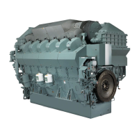
7. Do not blow a spray from the steam cleaner nozzle
at the alternator.
t
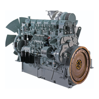
9.2.3 Testing voltage setting
1. Connect the alternator to a 12 volt battery with an
ammeter, a voltmeter and a switch as shown in the
illustration.
2. The voltmeter reading must be zero (0) when the
starter switch is in OFF position. It must be lower
than the battery voltage when the switch is in ON
position (the engine will not start).
3. With one ammeter lead short-circuited, start the
engine.
4. Read the voltmeter when the ammeter reading is
below five amperes and the engine is running at
1800 min–1 and also at 2500 min–1 with all
electrical loads turned off. The voltage setting
varies with alternator temperature. Generally, the
higher the alternator temperature, the lower the
voltage setting.
t
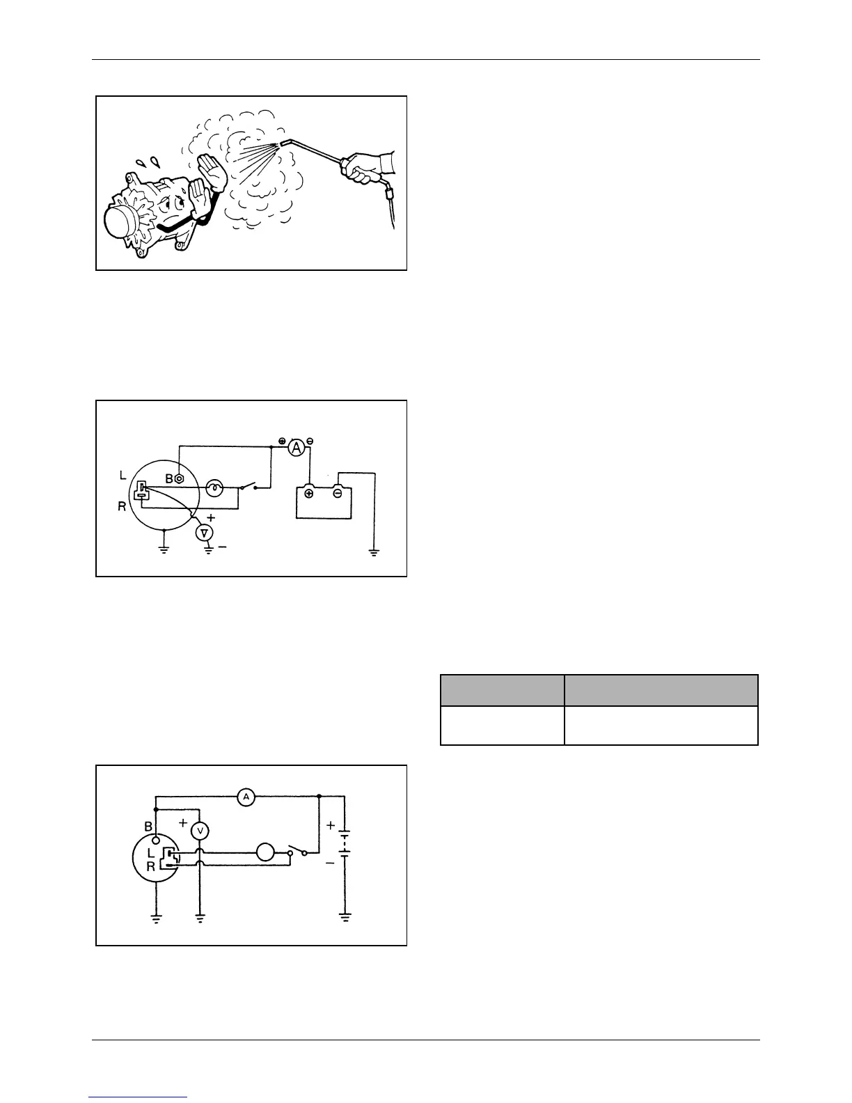
9.2.4 Testing output characteristics
1. Disconnect the battery ground (negative) cable.
2. Connect one ammeter lead to the B terminal of the
alternator and the other lead to the positive
terminal of the battery. Connect one voltmeter
lead to the B terminal and the other lead to the
ground.
3. Connect the battery ground cable.
4. Start the engine.
5. Turn on all electrical loads.
6. Increase the engine speed. Measure the
maximum output current at the specified alternator
speed when the voltmeter reading is 13.5 volts.
Figure 14 Connections for testing voltage setting
Ammeter
Battery
(12 volts)
Voltmeter
Switch
Item Standard
Voltage setting [at
20°C (68°F)]
14.7 ± 0.3 V
Figure 15 Connections for testing output
characteristics (alternator with built-in regulator)
Ammeter
Battery
Alternator
indicator light
Switch
 Loading...