Note
- Be sure not to misplace the removed
terminal block covers and screw.
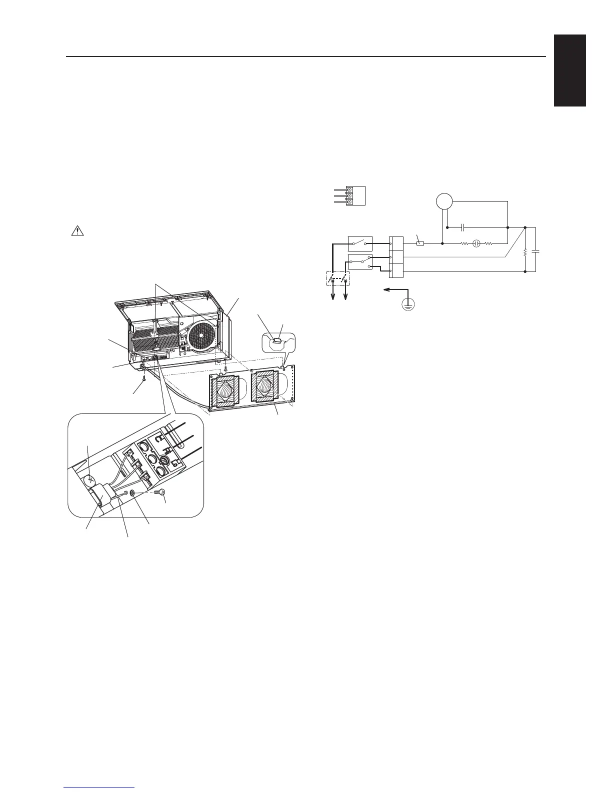
4) Pull the power and connection cables through
theholeintherearoftheunit.(Thecables
enter the room at the power/connection cable
pull-outposition.)
5)
Hangthecatchholesofthemainunitontothe
catchesofthemountingplate.(Bothsides)
6) Press the main unit into the wall and attach it
with the two screws provided.
Caution
- Tighten the two screws securely. (The joint
gap could cause the wall to become dirty.)
-Usethewasheratthepositionsasillsutrated.
7) Connect the Lossnay wiring.
Washer
Catchholes(onrearofmainunit)
Main unit
mounting screws
Power/
connection
cables
Catch
Catch hole
Mounting
plate
Main unit
Power/
connection
cable pullout
position
Cord clamp
mounting
screw
Ground screw
Cord
clamp
Ground wire
Operation requires a control switch.
Have a control switch ready and
connect the wiring shown in bold on
the connection diagram below.
Suitablecables:ø0.5toø2.0mmdiameter
Removethecoveringfromthenal10mmofthe
power and connection cables and screw the ends
in place on the terminal block.
8) Attach a ground cable to the terminal block
with a ground screw to ensure the unit is
grounded.
9) Fix the power and grounding wires in place
with the cord clamp.
10)Makesurethatthewireshavenotcome
loosefromtheterminalblock.
11)ScrewonterminalblockcoverB,andthen
re-mountterminalblockcoverAatitsoriginal
position.
12)Lowerthepanelandcloseit.
13)Turnthecircuitbreakeronatthedistribution
board.
C
Hi
Lo
Lo
Hi
COM
M
Operating indicator
Currentfuse
1.0A
Motor
Isolator
 Loading...