-
11
-
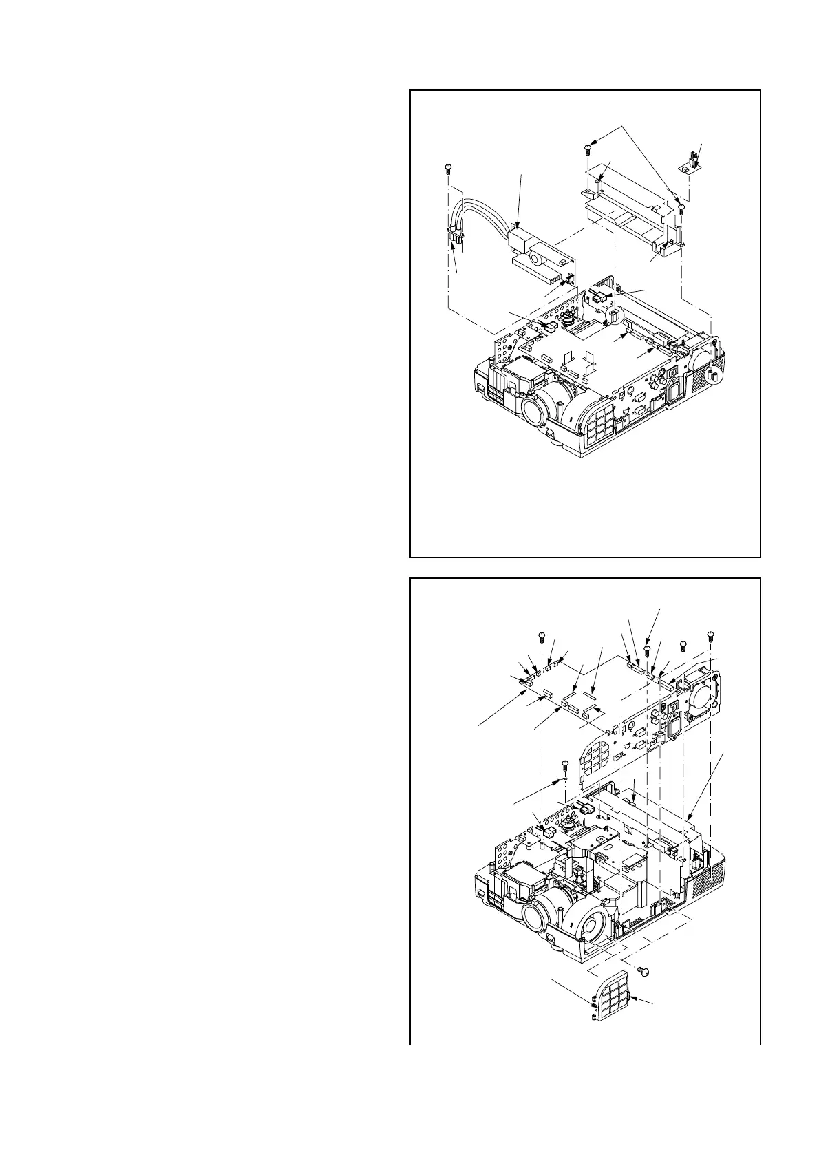
3. Removal of PREAMP PCB ASSY and
LAMP POWER UNIT
1. Remove the Top Case Assy and the Terminal Board
following “1.Removal of TOP CASE ASSY and
SPEAKER”. (Fig. 3-1)
2. Disconnect the two connectors (SA, SL) on the MAIN
PCB ASSY as shown in Fig. 3-3.
3. Disconnect the A and the B connectors on the Thermal
Protector as shown in Fig. 3-3.
4. Remove the two (a) screws and the Lamp Power
Connector as shown in Fig. 3-3.
5. Remove the two (b) screws and take out the Lamp
Power Assy.
6. Release the (c) hook and remove the PREAMP PCB
ASSY as shown in Fig. 3-3.
7. Release the (d) hook and remove the LAMP POWER
UNIT as shown in Fig. 3-3.
Note: Also disconnect the CN1 connector when removing
the LAMP POWER UNIT.
Fig. 3-4
4. Removal of TERMINAL ASSY
(MAIN PCB ASSY, INLET PCB ASSY,
TERMINAL PCB ASSY)
1. Remove the Top Case Assy and the Terminal Board
following “1.Removal of TOP CASE ASSY and
SPEAKER”. (Fig. 3-1)
2. Release the (a) hook and remove the Filter Cover as
shown in Fig. 3-4.
3. Remove the four (b) screws, the (c) screw, the (d)
screw and the three (e) screws as shown in Fig. 3-4.
4. Disconnect the fifteen connectors (SA, SB, SD, SF, SG,
SJ, SL, SN, SP, SR, SV, SW, SX, SY and SZ) on the
MAIN PCB ASSY as shown in Fig. 3-4.
5. Open the Power Barrier slightly and disconnect the RE
connector on the POWER PCB ASSY and the A and the
B connectors on the Thermal Protector as shown in Fig.
3-4.
6. Remove the Terminal Assy (MAIN PCB ASSY, INLET
PCB ASSY and TERMINAL PCB ASSY) as shown in
Fig. 3-4.
Note: Also remove the (f) screw of the Power Assy and
the earth wire from the Terminal Shield.
 Loading...