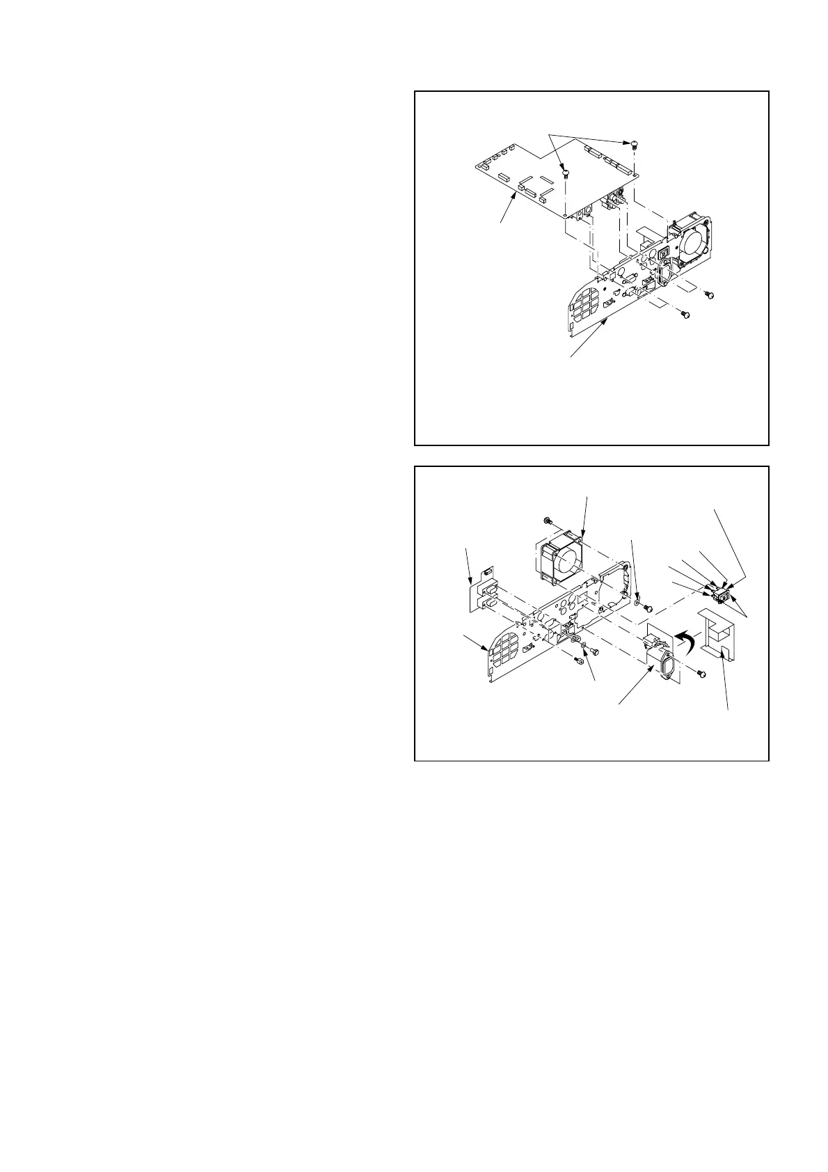
Fig. 3-5-2
5. Removal of MAIN PCB ASSY, INLET
PCB ASSY, TERMINAL PCB ASSY,
TERMINAL SHIELD and
COOLING FAN (POWER)
1. Remove the Top Case Assy and the Terminal Board
following “1.Removal of TOP CASE ASSY and
SPEAKER”. (Fig. 3-1)
2. Remove the Terminal Assy (MAIN PCB ASSY, INLET
PCB ASSY, and TERMINAL PCB ASSY) following
“4.Removal of TERMINAL ASSY (MAIN PCB ASSY,
INLET PCB ASSY, and TERMINAL PCB ASSY) ”. (Fig.
3-4)
3. Remove the two (a) screws, (b) screw, two (c) screws
and MAIN PCB ASSY as shown in Fig. 3-5-1.
Note: The number of screws b is follows:
SL2U 1 screw
XL2U 2 screws
4. Remove the four (d) screws and TERMINAL PCB
ASSY as shown in Fig. 3-5-2.
5. Remove the two (e) screws, (f) screw and the Cooling
Fan (Power) as shown in Fig. 3-5-2.
6. Remove the Inlet Barrier as shown in Fig. 3-5-2.
7. Disconnect the four connectors (FR, FS, FT, FU) on the
Seesaw SW as shown in Fig. 3-5-2.
8. Release the two (g) hooks and remove the Seesaw SW
as shown in Fig. 3-5-2.
9. Remove the two (h) screws, (i) screw and (j) washer
as shown in Fig. 3-5-2.
10. Turn the INLET PCB ASSY 90 degrees in the direction
of the arrow to remove it as shown in Fig. 3-5-2.
 Loading...