OPERATION
§4 Installation & Operation
§4.1 Installation & Operation for MIG Welding
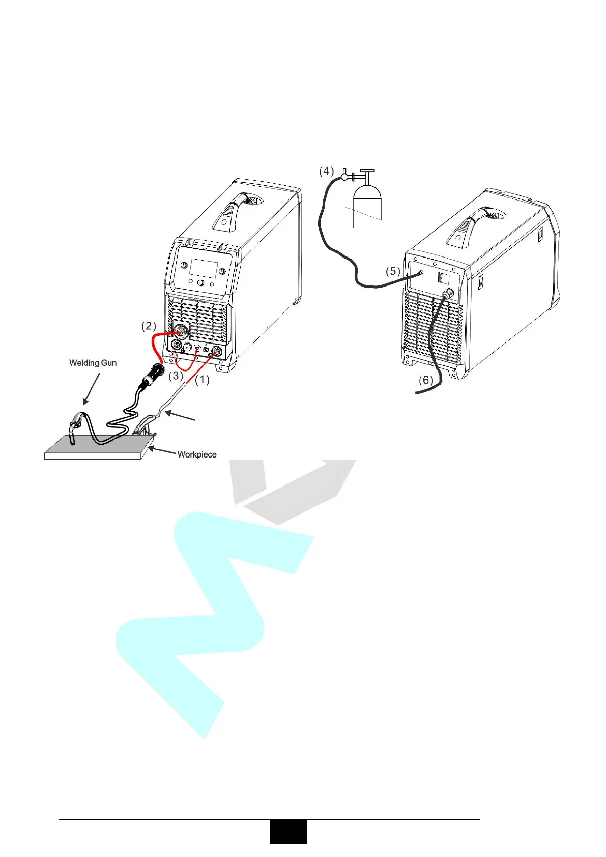
§4.1.1 Set up installation for MIG/MAG Welding
(1) Insert the earth cable plug into the negative socket on the front of the machine and tighten it.
(2) Plug the welding torch into the MIG torch connection socket on the front panel and tighten it.
IMPORTANT : When connecting the torch be sure to tighten the connection. A loose connection
can result in the connector arcing and damaging the machine and gun connector.
(3) Connect the MIG power connection lead to the positive welding power output socket.
Note if this connection is not made, there will be no electrical connection to the welding torch!
(4) Connect the gas regulator to the Gas Cylinder and connect the gas line to the Gas Regulator.
Check for Leaks!
(5) Connect the gas line to gas connector on the rear panel. Check for Leaks!
(6) Connect the power cable of welding machine with the output switch in electric box on site.
(7) Place the Wire Spool onto the Spool Holder. Snip the wire from the spool being sure to hold the
wire to prevent rapid uncoiling. Feed the wire into the wire feeder inlet guide tube through to the
drive roller.
(8) Carefully feed the wire over the drive roller into the outlet guide tube, feed through about 150mm
 Loading...