Connecting the unit
30 Installation instructions
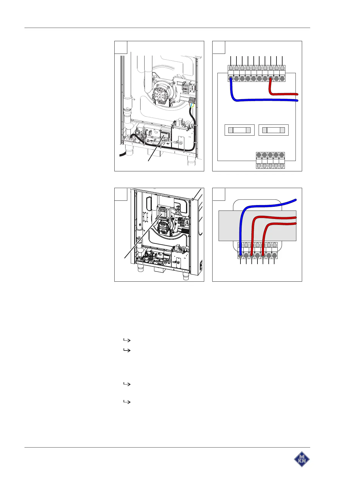
A B
N
nc
110 V
120 V
200 V
208 V
220 V
230 V
240 V
250 V
X1
X2
T1
Image: A Transformer position T1; B Connection for transformer controls
480 V
440 V
400 V
242 V
230 V
219 V
0 V
A B
T0
Image: A Transformer position T0, only for unit without neutral wire; B Transformer
connection
Requirement Unit not live
Left side wall removed
1. Measure the connection voltage with a suitable measuring device.
The voltage range must match that on the nameplate.
If there are voltage fluctuations, the maximum expected
voltage must be taken into account.
2. Check whether the transformer voltage is within the specified
range (see "Equipment and connection data").
If the set voltage differs, match the transformer voltage by
reconnecting.
Document the new voltage set on the sticker.
3. In the case of units with several transformers, repeat the
procedure for each transformer.
4. Close the housing (see "Opening and closing the housing").
5. Fill out the Commissioning report.
10013865-0AIBE-B