EasyManua.ls Logo

MKS RGA Series - Position Feedback Signals; Pinouts; Motor Connector; Encoder Connector

MKS RGA Series
32 pages
Print Icon
To Next Page IconTo Next Page
To Previous Page IconTo Previous Page
Loading...
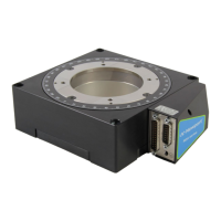
RGA Series Low profile fast rotation stage
A1355A0 EDH0427En1010 – 04/21 8
4.3 Position Feedback Signals
The incremental sensor consists of an optical scale and an encoder head.
When the carriage moves, the encoder head generates signals in quadrature
and sends them to the pins of the encoder connector.
4.4 Pinouts
The pinout diagrams for RGA stage connectors are shown below.
4.4.1 Motor Connector
4.4.2 Encoder Connector
14
Motor Earth
15
N.C.
16
GND
17
Do not connect
18
Do not connect
19
N.C.
20
N.C.
21
Do not connect
22
GND
23
N.C.
24
N.C.
25
N.C.
SUB-D25M
1
Phase L Motor
2
Phase L Motor
3
N.C.
4
N.C.
5
Phase M Motor
6
Phase M Motor
7
Phase N Motor
8
Phase N Motor
9
Thermistor
10
N.C.
11
N.C.
12
N.C.
13
Do not connect
SUB-D15M
1
Encoder Phase A
2
GND
3
Encoder Phase B
4
+5V
5
N.C.
6
N.C.
7
Index Pulse /I
8
N.C.
9
Encoder Phase /A
10
N.C.
11
Encoder Phase /B
12
N.C.
13
Do not connect
14
Index Pulse I
15
Do not connect

Related product manuals