22
Visit our website at http://modeltech.globalhobby.com or for Customer Service at http://globalservices.globalhobby.com
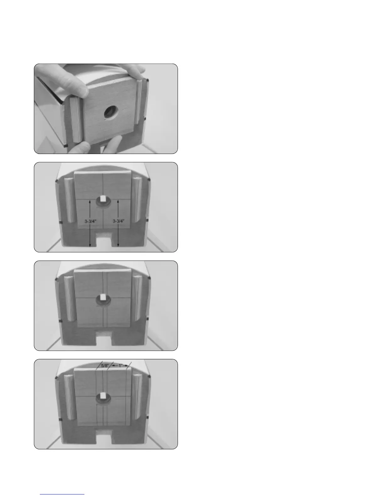
❑ Using a ruler and a pencil, draw a vertical centerline on
the firewall.
❑ Using a ruler and a pencil, measure 3-3/4" up from the
bottom of the firewall and draw a horizontal line. This will be
referred to the "horizontal thrust line."
❑ Measure 1/4" to the right of the vertical centerline and
draw a second vertical line parallel to it.
☞
This second vertical line will be referred to as the "vertical
thrust line."
Step 1: Aligning the Engine Mounting Beams
IMPORTANT If you'll be using an engine that is smaller
than 1.08 - 1.20 size, begin by epoxying on the plywood spacer
as described below. If you'll be using a 1.08 - 1.20 size
engine, skip this procedure. The plywood spacer does not
need to be installed.
❑ Carefully line up the plywood spacer onto the firewall and
glue it into place using a generous amount of 5 minute epoxy.
To line it up properly, the predrilled hole in the spacer should
line up with the predrilled hole in the firewall and the sides of
the spacer should be parallel to the firewall supports.
❑ Using a ruler and a pencil, measure and draw a vertical
line 1" to the right of the vertical thrust line.
❑ Measure and draw a vertical line 5/8" to the left of the
vertical thrust line.
☞
Do not measure from the centerline. Measure from the
vertical thrust line.