30
Visit our website at http://modeltech.globalhobby.com or for Customer Service at http://globalservices.globalhobby.com
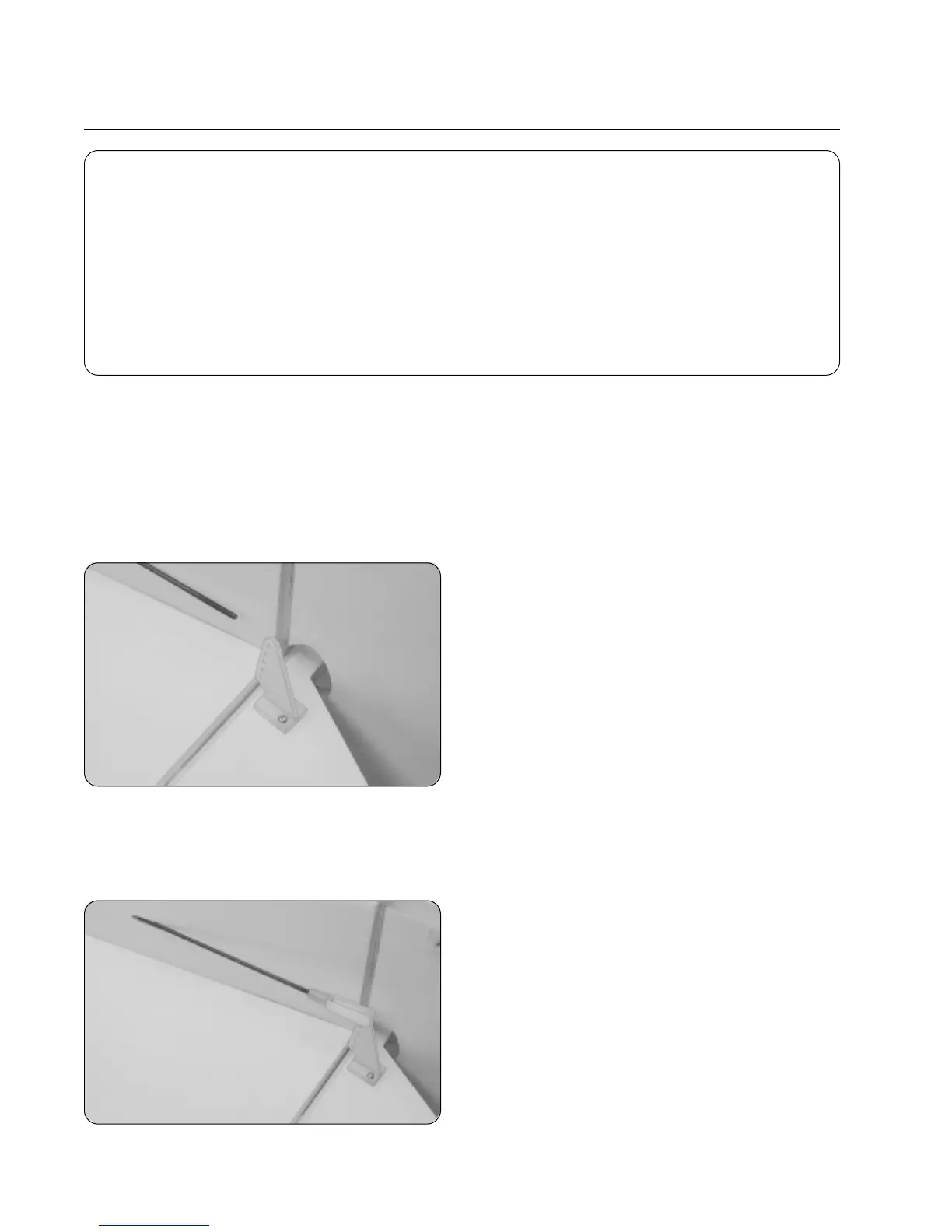
❑ Position one nylon control horn onto the bottom of the
elevator, aligning the control horn with the pushrod wire. The
centerline of the control horn should be about 5/8" out from
the side of the fuselage.
❑ Angle the control horn about 1/16" toward the fuselage
side so it will line up better with the pushrod wire and adjust the
control horn so that the clevis attachment holes are directly
over the hinge line.
❑ Mark the positions of the control horn mounting screws, then remove the control horn and set it aside.
❑ Drill the holes through the elevator for the mounting screws using a 5/64" diameter drill bit.
❑ Install the control horn and backplate using two 2mm x 20mm machine screws, being careful not to overtighten them.
❑ Thread one clevis onto the pushrod wire and snap it into
the outermost hole in the control horn.
☞
Hold the pushrod wire with a pair of pliers to prevent it
from turning while installing the clevis.
❑ # 1 Phillips Head Screwdriver
❑ Wire Cutters
❑ Needle Nose Pliers
❑ Excel Modeling Knife
❑ Electric Drill
YOU'LL NEED THE FOLLOWING PARTS FROM THE KIT:
❑ (2) 31" Threaded Wires
❑ (2) Nylon Control Horns w/Backplates
❑ (4) 2mm x 20mm Machine Screws
SECTION 17: ELEVATOR & RUDDER CONTROL SYSTEM INSTALLATION
❑ (2) Nylon Clevises
❑ (2) Nylon 90º Snap Keepers
YOU'LL NEED THE FOLLOWING TOOLS AND SUPPLIES:
❑ 5/64" Drill Bit
❑ Ernst Airplane Stand
❑ Ruler
❑ Pencil
❑ Masking Tape
Step 1: Installing the Elevator Pushrod Assembly
❑ Using a modeling knife, cut away and remove the covering material from over the elevator pushrod exit hole in the right
side of the fuselage. The hole is located 4-1/4" in front of the rudder hinge line and 7/8" below the horizontal stabilizer.
❑ Slide one 31" long pushrod wire (plain end first) into the preinstalled pushrod housing in the fuselage side.
❑ Use a couple of pieces of masking tape to hold the elevator centered.