31
Need help or have any questions? Call us at 1-714-963-0329 or send us an Email at service@globalhobby.net
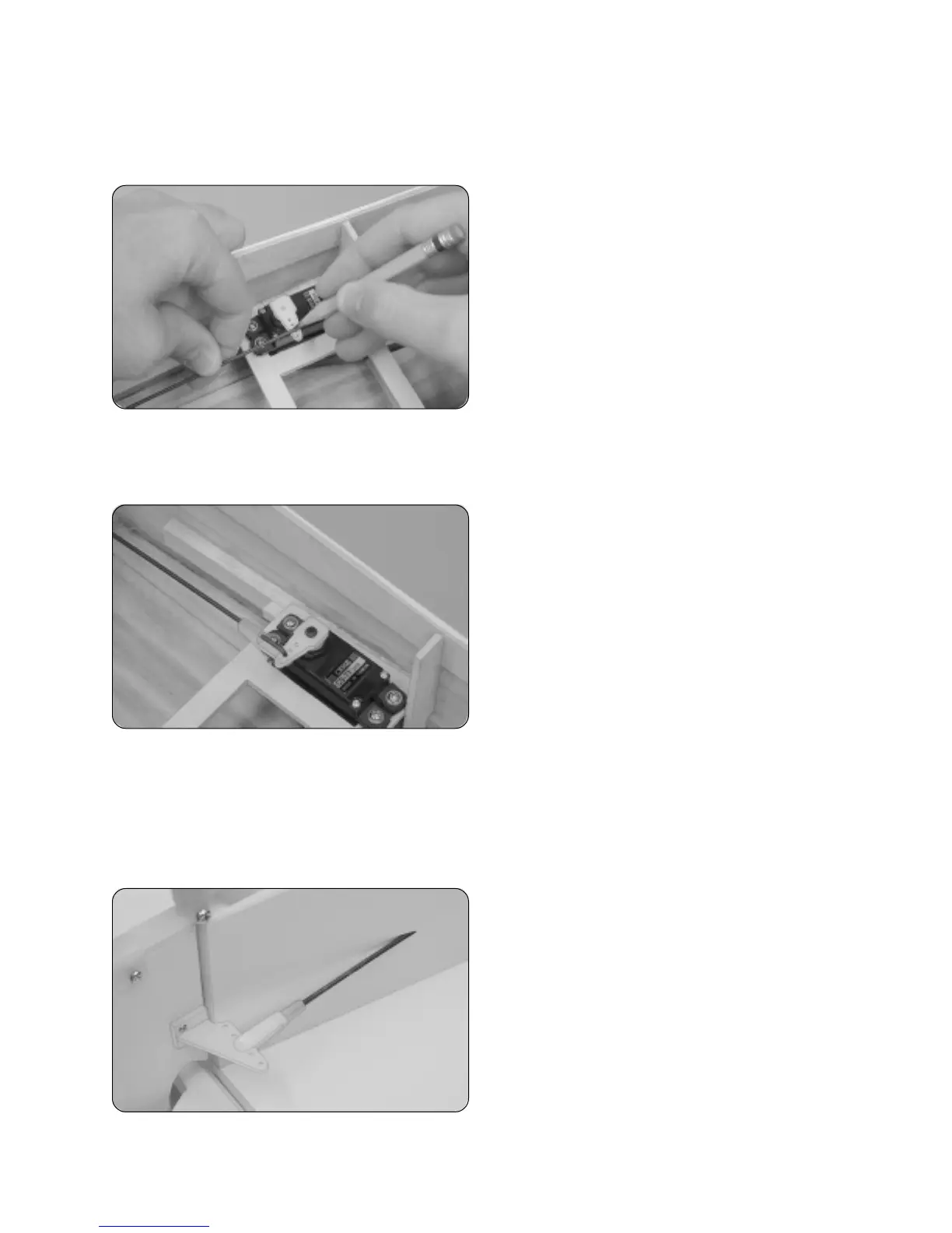
❑ Using a modeling knife, carefully cut away all but one arm from a large "4-point" servo horn.
❑ Enlarge the third hole out from the center of the servo arm using a 5/64" diameter drill bit.
❑ Connect your radio system, plug the elevator servo into
the receiver (the servo on the right side of the fuselage), then
center the servo.
❑ Attach the servo horn to the servo, making sure it's
centered and points toward the middle of the fuselage.
❑ With the elevator and the servo horn centered, draw a
mark on the elevator pushrod wire where it crosses the third
hole out from the center of the servo horn.
❑ Remove the clevis from the pushrod wire and slide the
threaded end of the wire into the pushrod housing from inside
the fuselage.
❑ Secure the pushrod wire to the servo horn using one
nylon 90º snap keeper.
❑ Install and tighten the servo horn retaining screw to
secure the servo horn to the servo.
❑ Unsnap the clevis from the control horn and remove the pushrod from the fuselage.
❑ Using a pair of pliers, carefully bend the pushrod wire down at a 90º angle (at the mark you drew) and cut off the
excess, leaving 5/16" of wire beyond the bend.
❑ Again, making sure that the elevator and the control horn are still centered, thread the clevis onto the pushrod wire and
snap it into the outermost hole in the control horn.
Step 2: Installing the Rudder Pushrod Assembly
❑ The rudder pushrod assembly is installed using the same
procedures as the elevator pushrod assembly. Snap the clevis
into the third hole out from the base of the control horn.
☞
The rudder control horn should be installed 1-3/4" up from
the bottom of the rudder. Adjust the control horn so that the
base of the control horn is parallel to the hinge line and the
clevis attachment holes are over the hinge line.
❑ Using a modeling knife, cut away and remove the covering material from over the rudder pushrod exit hole in the left
side of the fuselage. The hole is located 2-7/8" in front of the rudder hinge line and 1" below the horizontal stabilizer.