28
Visit our website at http://modeltech.globalhobby.com or for Customer Service at http://globalservices.globalhobby.com
❑ Remove the servo tray. Using a modeling knife, cut away and remove the covering material from within the outline
you drew.
❑ Glue the servo tray into place using a generous amount of 5 minute epoxy. Remove any excess epoxy using a paper
towel and rubbing alcohol, and allow the epoxy to set up before proceeding.
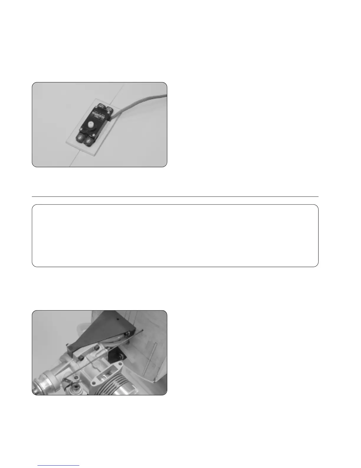
❑ Install the aileron servo into the servo tray, making sure
the servo output shaft is toward the trailing edge of the wing.
☞
To make it easier to install the servo mounting screws,
first drill 1/16" pilot holes through the servo tray.
IMPORTANT Use a modeling knife to cut a small notch in
the side of the servo tray for the aileron servo lead to exit.
❑ Kwik Bond Thin C/A
❑ # 1 Phillips Head Screwdriver
❑ Wire Cutters
❑ Needle Nose Pliers
YOU'LL NEED THE FOLLOWING PARTS FROM THE KIT:
❑ (1) 17-3/4" Pushrod Wire w/Z-Bend
SECTION 16: THROTTLE LINKAGE INSTALLATION
❑ (1) Adjustable Servo Connector Assembly
YOU'LL NEED THE FOLLOWING TOOLS AND SUPPLIES:
❑ Excel Modeling Knife
❑ Electric Drill
❑ 5/64" Drill Bit
❑ Ernst Airplane Stand
Step 1: Installing the Throttle Pushrod Wire
❑ Remove the throttle arm from your engine and install the Z-Bend in the pushrod wire into the outermost hole in the
throttle arm.
❑ Slide the pushrod through the hole you drilled previously
in the firewall and reinstall the throttle arm onto your engine.
Step 2: Installing the Adjustable Servo Connector
❑ Using a modeling knife, carefully cut away all but one arm from a large "4-point" servo horn.