41
Need help or have any questions? Call us at 1-714-963-0329 or send us an Email at service@globalhobby.net
SECTION 27: OPTIONAL REAR-MOUNTED ELEVATOR & RUDDER SERVOS
This section describes installation of the optional rear-mounted elevator and rudder servos. As stated previously, we
suggest installing the elevator and rudder servos in the back of the fuselage if you will be using larger, heavier engines.
This will help balance the airplane without having to add extra weight to the tail.
❑ Remove the covering material from over the two precut servo mounting holes in the fuselage sides. The elevator
servo mounting hole is located in the right side of the fuselage, 7-1/2" in front of the rudder hinge line and 1-3/4" up from
the bottom of the fuselage. The rudder servo mounting hole is located in the left side of the fuselage, 6" in front of the
rudder hinge line and 1" up from the bottom of the fuselage.
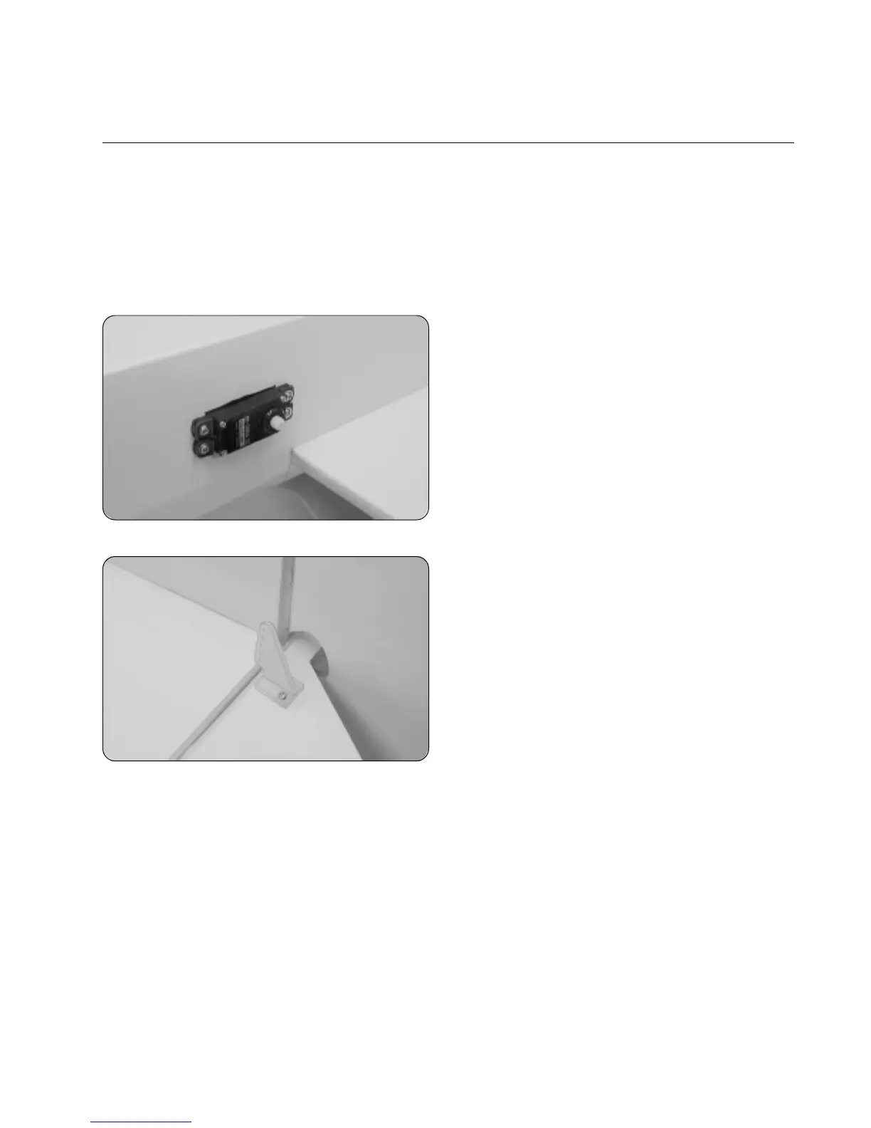
❑ Install the elevator and rudder servos into the servo
mounting holes, making sure the servo output shafts are
toward the back of the fuselage.
IMPORTANT When installing the elevator servo, carefully
push the two nylon pushrod housings up while sliding the
servo into place.
☞
To make it easier to install the servo mounting screws,
first drill 1/16" pilot holes through the fuselage sides.
❑ Position one nylon control horn onto the bottom of the
elevator. The centerline of the control horn should be 5/8"
out from the side of the fuselage and the base of the control
horn should be parallel to the elevator hinge line. Make sure
that the clevis attachment holes are directly over the hinge
line, too.
❑ Use a couple of pieces of masking tape to hold the elevator centered.
❑ Mark the positions of the control horn mounting screws, then remove the control horn and set it aside.
❑ Drill the holes through the elevator for the mounting screws using a 5/64" diameter drill bit.
❑ Install the control horn and backplate using two 2mm x 20mm machine screws, being careful not to overtighten them.
❑ Thread one clevis onto one 31" long threaded pushrod wire and snap it into the third hole out from the base of the
control horn.
☞
Hold the pushrod wire with a pair of pliers to prevent it from turning while installing the clevis.
❑ Using a modeling knife, carefully cut away all but one arm from a large "4-point" servo horn.
❑ Enlarge the third hole out from the center of the servo arm using a 5/64" diameter drill bit.