32
Visit our website at http://modeltech.globalhobby.com or for Customer Service at http://globalservices.globalhobby.com
❑ Install the rudder pushrod into the third hole out from
the center of the servo horn. Also, don't forget to install and
tighten the servo horn retaining screw.
❑ # 1 Phillips Head Screwdriver
❑ Needle Nose Pliers
❑ Excel Modeling Knife
YOU'LL NEED THE FOLLOWING PARTS FROM THE KIT:
❑ (2) 4-1/2" Threaded Wires w/90º Bend
❑ (2) Nylon Adjustable Control Horns
SECTION 18: AILERON CONTROL SYSTEM INSTALLATION
❑ (2) Nylon Clevises
❑ (2) Nylon 90º Snap Keepers
YOU'LL NEED THE FOLLOWING TOOLS AND SUPPLIES:
❑ Electric Drill
❑ 5/64" Drill Bit
❑ Masking Tape
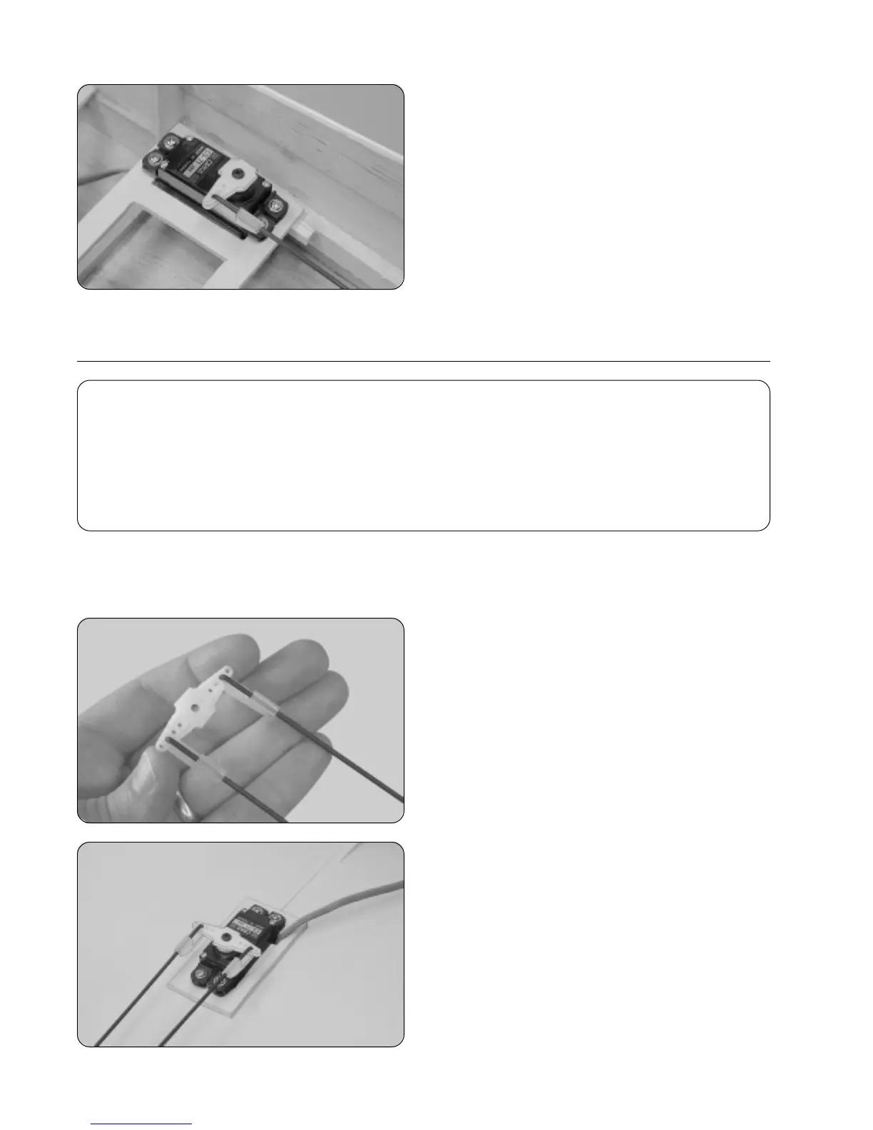
Step 1: Installing the Aileron Pushrod Assembly
❑ Using a modeling knife, cut away two arms from a large "4-point" servo horn.
❑ Enlarge the third hole out from the center of each servo
arm using a 5/64" diameter drill bit.
❑ Install the 90º bend in each aileron pushrod wire into the
holes that you just enlarged, using the snap keepers provided.
☞
The pushrod wires should be on top of the servo arms
as shown.
❑ Center the aileron servo and install the servo arm
assembly making sure that the servo arm is centered.
❑ Install and tighten the servo arm retaining screw.