20
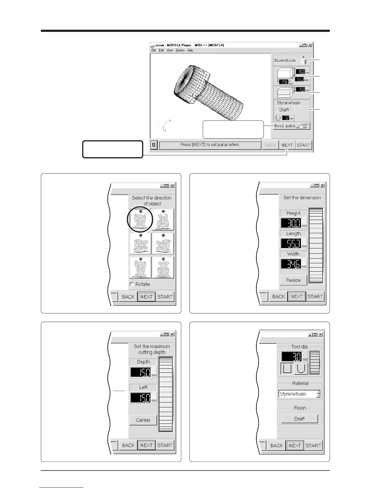
Make the settings for the cutting condi-
tions. Clicking [NEXT] advances the
setting screens in sequence from A to D.
Make the settings in order from A to D.
(Clicking A, B, C, or D in the figure
displays the corresponding setting screen,
this should not be used except when it's
necessary to make settings independently.)
C
Set the maximum
cutting depth
Make the setting for the
maximum cutting depth.
Drag the spin dial up or
down, or click on a number
and enter a value from the
keyboard.
Clicking [Center] sets the
depth at a location
proportional to the height.
D
Tool diameter/
Material/Finish
Tool
Set the type and diameter
of the tool that is installed.
Material
Choose the composition of
the loaded workpiece.
Finish
When cutting a solid object
on a modeling machine, an
attractive finish can be
obtained by first perform-
ing rough (draft) cutting,
then performing fine
cutting. Set to [Draft] for
the first pass, and to [Fine]
for the second pass.
This displays the path of
the tool during cutting.
Click here to advance to
the next settings.
A
B
C
D
A
Select the direction
of the object
Select the direction to be
used for cutting the object.
In the figure at right,
cutting from above is
selected.
B
Set the dimension
Make the setting for
object's size. Drag the spin
dial up or down, or click
on a number and enter a
value from the keyboard.
Clicking [Resize] makes it
possible to specify a ratio
for the dimensions.