2
MODINE CONTROLS SYSTEM MANUAL
ClassMate and SchoolMate Models
AIR74-525.1
2
General Information
Table of Contents
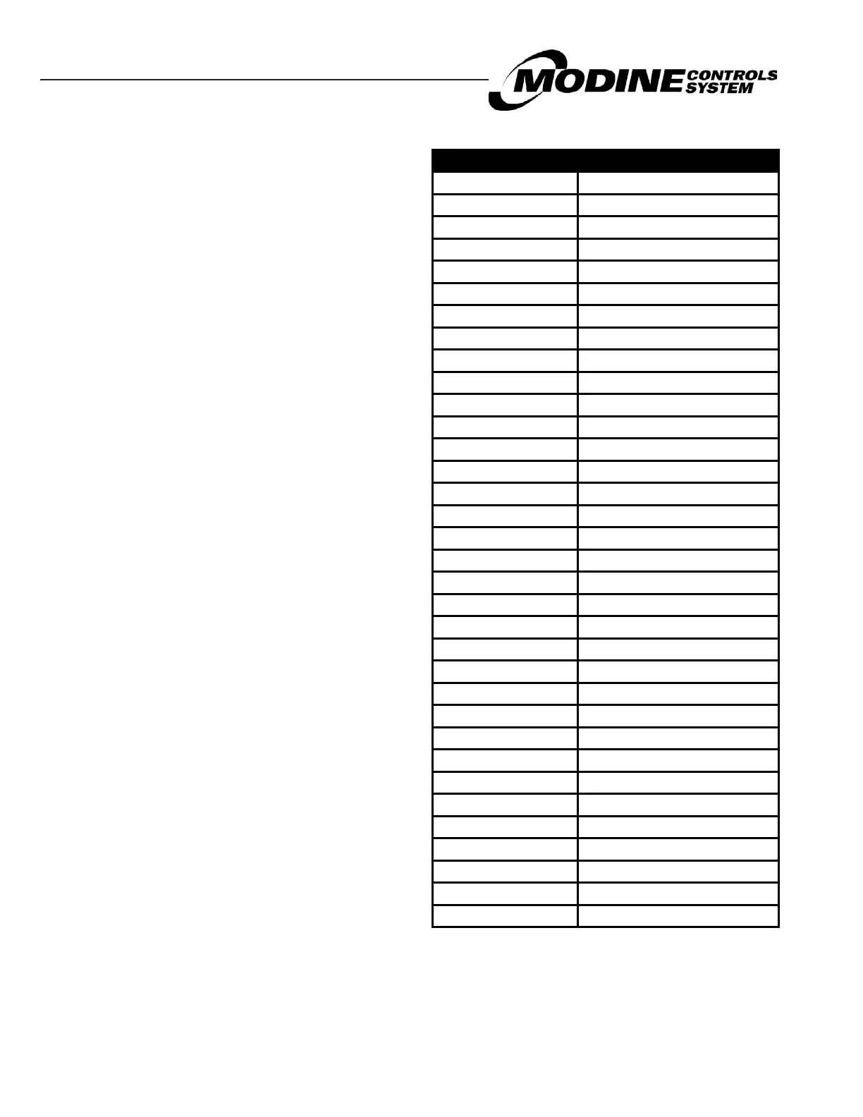
Table 2.1 - Acronyms Used
Controls are one of the most important components of
specialized HVAC equipment. The Modine Controls
System is designed and engineered for the ClassMate and
SchoolMate units to ensure that they will operate safely,
reliably, with optimized performance, and maintain maximum
energy efficiency.
Acronyms Commonly Used In Controller.................................2
Controller Overview...............................................................3
Description and Features..........................................3
Standard and Optional Sensors Monitored................3
Model Nomenclature - ClassMate...........................................4
Model Nomenclature - SchoolMate.........................................4
Figure 8.1 pCOOEM+ Controller Layout.....................3
Display/Keypad Functions.....................................................6
Table 9.1 Standard Buttons......................................10
Table 9.12 Extra Function Button Sequences............10
Menu Navigation.....................................................11
Table 10.1 Navigation Sub Menus............................11
Example Navigation to On/Off Sub Menus.................11
Password Protection..............................................12
Adjusting Customer Control Settings.......................12
Main Menu – Tree of Functions..............................................12
Main Status Screen Parameters..............................10
On/Off SubMenu..................................................................13
SetpointSub Menu...............................................................14
Clock/Scheduler Sub Menu..................................................15
Input/Output Sub Menu........................................................14
Data Logger Sub Menu.........................................................15
Board Switch Sub Menu........................................................12
Remote Display Keypad to Controller.......................10
Service Sub Menu................................................................16
Information............................................................16
Working Hours........................................................17
BMS Configuration.................................................17
Work Hour Setpoint.................................................18
Probe Adjustment...................................................19
Manual Management..............................................17
Analog Input...........................................................18
Digital Input............................................................19
Relay Output..........................................................19
Analog Output........................................................19
Unit Alarms..........................................................................20
Main Unit Controller Inputs/Outputs......................................22
Typical BMS – EMS – BAS System Variables..........................23
Acronym Phrase
BMS Building Management System
BPS Bits Per Second
CCS Capacity Control Solenoid
CF Condenser Fan
CFM Cubic Feet per Minute
Comp Compressor
Dehum De-humidify
Diff Difference
EA Exhaust Air
Econ Economizer
Elec Electric
ERV Energy Recovery Ventilator
Ex Exhaust
HGRH Hot Gas Re-Heat
hr Hour
Ht Heat
ID Fan Indoor Fan
LL Liquid Line
min “Minutes” or “Minimum”
Mod Mode
OA Outside Air
Perc Percentage “%”
psig Pounds per Square Inch gage
RA Return Air
Rev Vl Reversing Valve
RH Relative Humidity
s Seconds
SA Supply Air
SetPt Setpoint
Sp Speed
St-by Standby
Str Start
Temp Temperature
Vlv valve