Engineering
28
04/99 AWB 2700-1311 GB
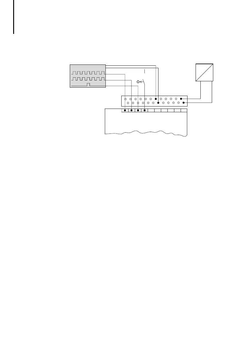
Connecting incremental encoders
Figure 12: Connecting an incremental encoder
햲
Incremental encoder
햳
Output signals from the incremental encoder
햴
Valid reference signal range
햵
Power supply for the incremental encoder
햶
Power supply unit for the incremental encoder (follow
manufacturer’s instructions for the incremental
encoder)
햷
Digital inputs (multi-function inputs)
햸
ZB 4-122-KL1 twin-level terminal block
24 V incremental encoders with A, B, and C signals
may be connected.
Signal B is offset 90° from signal A. This phase shift
is used to determine the direction of rotation. If the
rising edge of the A signal appears at the PS 4-300’s
signal input before the rising edge of the B signal,
clockwise rotation can normally be assumed. If the
rising edge of the B signal appears before that of the
A signal, the direction of rotation is normally anti-
clockwise.
햲
햷
햳
햸
햵
+24 V
0 V
0 V
I
+Vcc
+Vcc
햴
햶
=
~
0 V
.0
.1
.2
.3
.4
.5
.6
.7
0
Track C
Track B
Track A
H1311g.bk Seite 28 Freitag, 4. Juni 1999 1:12 13
 Loading...
