SST-PB3S-CLX-RLL User Reference Guide
Hardware Overview 13
©2014 Molex Inc. Industrial Products Business Unit, Integrated Products Division
Document Edition: 1.0, Document #: 715-0109, Template Edition: 1.1, Template #: QMS-06-045
Use, duplication or disclosure of this document or any of the information contained herein is subject to the restrictions on page ii of this document.
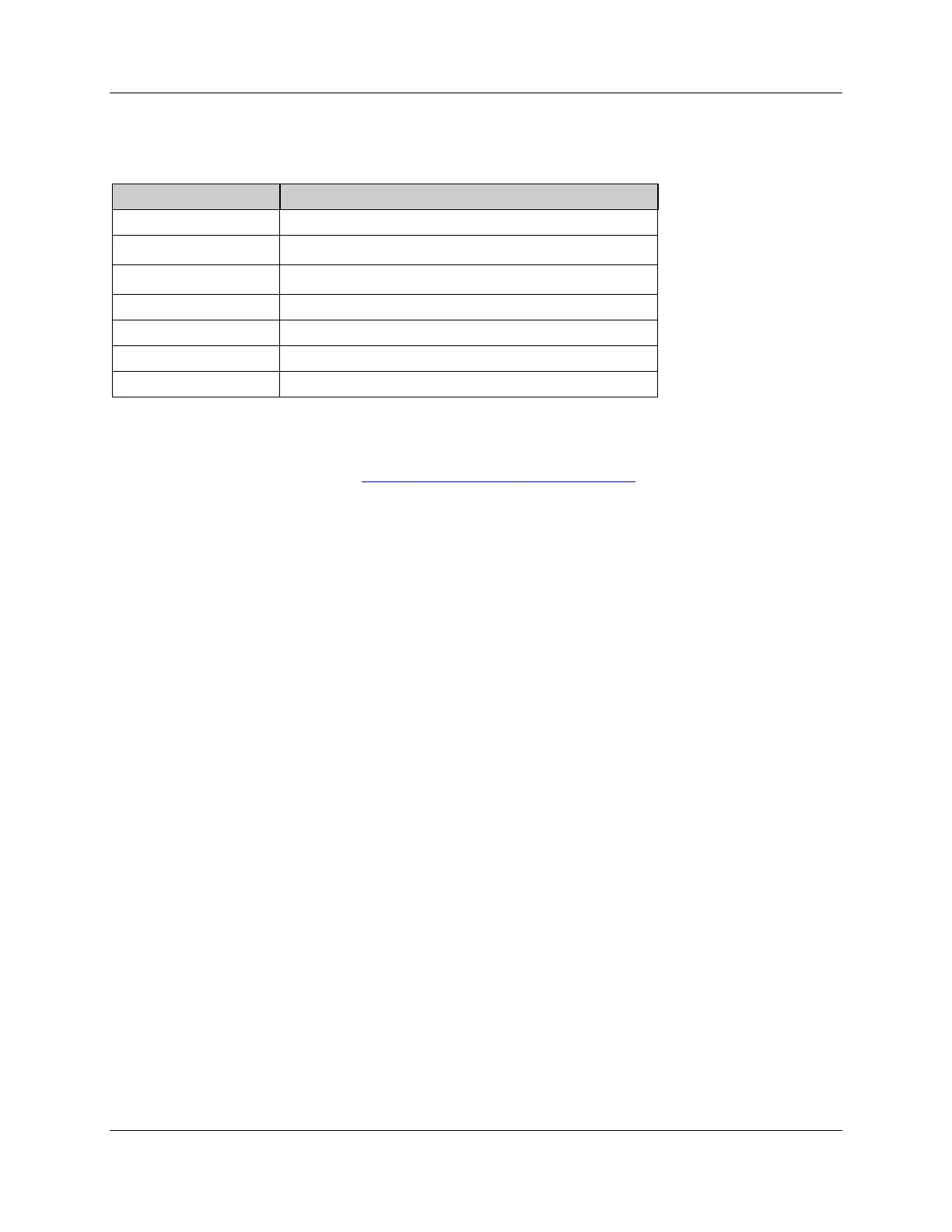
Table 1: Description of Features
Display the communication and system status
Identifies the device, ports and protects internal electronic
components from dust, contaminants and possible damage
For connection to the PROFIBUS network
Secure the slave in the chassis slot
Provides module information
CLX Connection status faults, operation status
For upgrading module firmware
2.1.1 Status LEDs
There are three LEDs on the module, the COMM LED, SYS LED and the OK LED. For detailed
information, refer to Section 4.3, PROFIBUS LED and Display States
.
COMM LED
The COMM LED remains off while the slave is online and operating correctly. The only time
this LED remains RED is when a fatal error occurs. The COMM and SYS LED will go red at the
same time to indicate an unrecoverable fatal error.
SYS LED
The SYS LED indicates the communication status with the PROFIBUS Slave. When the SYS
LED is solid red, the PROFIBUS Slave is no longer being scanned by a DP Master, and when it
is solid green, the PROFIBUS Slave is successfully being scanned by a DP Master in Run mode.
An amber SYS LED indicates that the PROFIBUS Slave is being successfully scanned by a DP
Master that is in Clear mode.
OK LED
The OK LED indicates that initialization is complete and that the module is OK.
2.1.2 9-Pin PROFIBUS Connector
The 9-pin PROFIBUS Connector connects the slave to the PROFIBUS network.
2.1.3 Configuration Port
Use the configuration port to upgrade module’s firmware.
 Loading...