SST-PB3S-CLX-RLL User Reference Guide
Installing the SST-PB3S-CLX-RLL Slave 27
©2014 Molex Inc. Industrial Products Business Unit, Integrated Products Division
Document Edition: 1.0, Document #: 715-0109, Template Edition: 1.1, Template #: QMS-06-045
Use, duplication or disclosure of this document or any of the information contained herein is subject to the restrictions on page ii of this document.
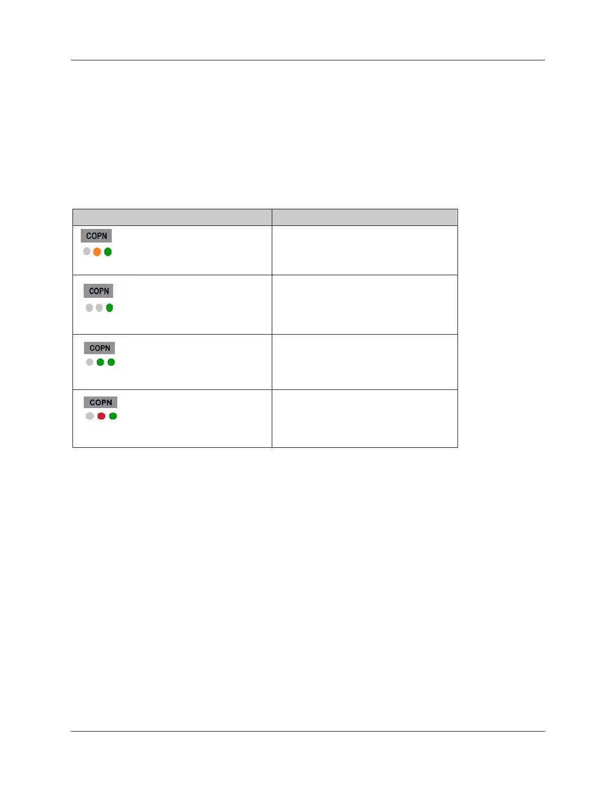
4.4 LED and Display Combinations
While a connection is open, COPN shows on the LCD Display. From left to right, the LEDs are
COMM, SYS and OK. The COM LED may go RED when the slave is first put online but then it
will remain off while the card is online.
Table 7: LED and Display Combinations
COPN State Description
OK LED green and SYS LED is amber.
Card is online and being scanned in CLEAR
mode by DP Master and the connection is open.
OK LED is green and COMM and SYS are off.
Card is offline and the connection is open.
SYS and OK LEDs are green. COMM is off.
Card is online and being scanned in RUN mode
by a DP Master and the connection is open
COMM is Off. SYS LED is red and OK LED is
GREEN.
Card is online and is not being scanned by a DP
Master.
 Loading...