SST-PB3S-CLX-RLL User Reference Guide
Installing the SST-PB3S-CLX-RLL Slave 23
©2014 Molex Inc. Industrial Products Business Unit, Integrated Products Division
Document Edition: 1.0, Document #: 715-0109, Template Edition: 1.1, Template #: QMS-06-045
Use, duplication or disclosure of this document or any of the information contained herein is subject to the restrictions on page ii of this document.
4.2 PROFIBUS Wiring
The module contains a standard DB9 connector, which can be connected to a PROFIBUS bus
terminal. The module has no built-in termination. If you require termination, you can use a
Bus terminal that has built-in selectable termination.
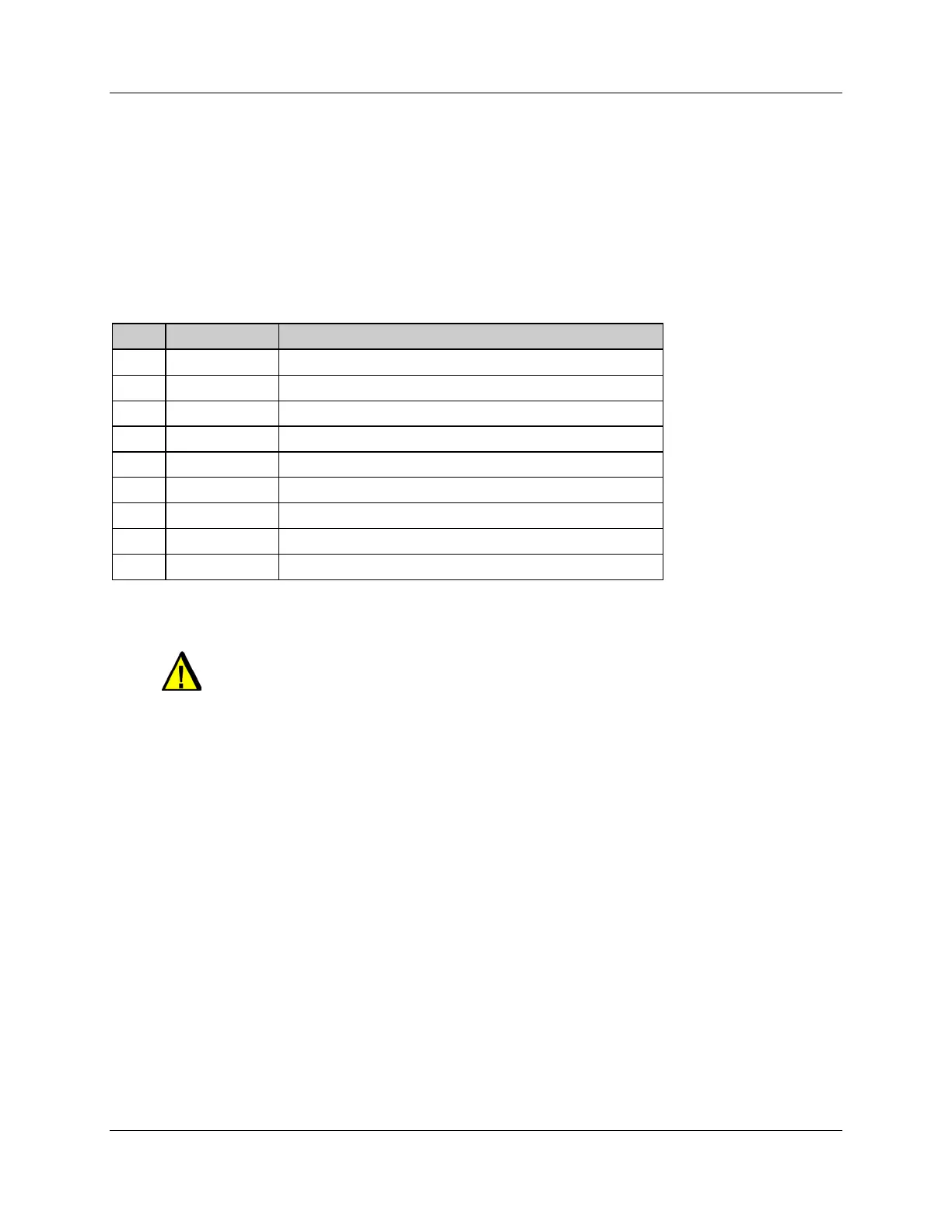
Table 2: DB9 Instructions
Pin # Pin Description DB9 Line * Termination When Using the SST-PB3S-CLX-RLL
1 Chassis ground
2 Reserved
3 Data + Connect this pin to pin 8 (data -) with 220 ohm resistor
4 TX Enable
5 Isolated ground Connect this pin to pin 8 (data -) with 390 ohm resistor
6 Isolated +5V Connect this pin to pin 3 (data +) with 390 ohm resistor
7 Reserved
8 Data -
9 Reserved
* For line A cable (135-165 ohm impedance)
Caution
Do not connect devices to the +5V line. It is there for termination
purposes only.
 Loading...