22
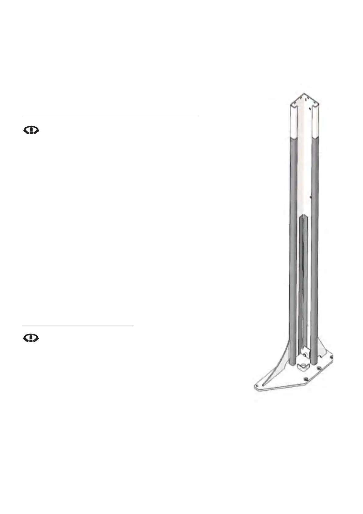
Diagram 38 –
Carriage Slide Block
Lubrication Track Areas
Inside of Post
14. Refit Cylinders, Balance Cables and Lock Release Cable.
15. Reactivate power supply for hoist.
16. Adjust balance cables, lock release cable and bleed hydraulic system.
17. Refit all covers and lower hoist to ground
CARRIAGE SLIDE BLOCKS
Carriage Slide Block Tracks Inspection and Lubrication
When cleaning Carriage Slide Block Tracks, refer Diagram
38, inspect for signs of wearing or scraping inside posts.
Significant long freshly made marks will indicate
requirement to fit new carriage slide blocks.
1. Rock each carriage front to back and side to side inside the post
to check for excessive clearance.
2. Lower hoist to ground remove top cylinder covers
3. Wipe clean the top section of tracks inside the posts and inspect.
4. Apply fresh grease to Carriage Slide Block Tracks in the areas
accessible above carriages.
5. Refit top cylinder covers, raise hoist to top lock and remove
bottom cylinder covers
6. Wipe clean the bottom section of tracks inside the posts and
inspect.
7. Apply fresh grease to Carriage Slide Block track in the areas
accessible below carriages.
8. Refit the bottom cylinder covers.
9. Run hoist through full cycle and remove covers to inspect tracks
grease coverage. Apply more grease in areas if necessary.
10. Lower hoist to ground.
Carriage Slide Block Replacement
When disassembling and reassembling the hydraulic
fittings, first mark an alignment point on both sides of the
fitting. The fitting must be retightened to the same torque
on reassembly to achieve correct seal. Refer to Diagram 3
and the Cylinder Replacement procedure.
1. Remove arms from carriage.
2. Lock hoist on first position
3. Isolate hoist from electrical power.
4. Remove Cylinder and Balance Cables and follow the Top
Balance Cable Pulley Replacement procedure until after the top
plate has been removed.
5. For the Control Post only, disconnect limit switch, disconnect
wiring*, disconnect hydraulic oil lines and remove power pack.