21
a. Run through the correct area of the carriage
b. Run over the correct pulleys
c. Correctly seated in the pulleys
d. Not twisted around the cylinder.
8. Conduct Balance Cable Adjustment procedure.
9. Replace cylinder covers.
TOP BALANCE CABLE PULLEY
When disassembling and reassembling the hydraulic fittings, first mark an alignment point
on both sides of the fitting. The fitting must be retightened to the same torque on
reassembly to achieve correct seal. Refer to Diagram 3 and the Cylinder Replacement
procedure.
Top Balance Cable Pulley Replacement
1. Lock hoist on first position
2. Isolate hoist from electrical power.
3. Remove the cable covers, disconnect lock
release cable from Non-Control Side locking
toggle and pull the lock release cable back to
the Control Side locking toggle and coil up over
handle to keep out of the way while working.
4. Remove both Balance Cables.
5. For both cylinders, follow the Cylinder removal
procedure to the end of Step 8; leave cap off
and the cylinders supported by the wedges.
6. Remove the top hydraulic pipe, secure plastic
bags over the ends with cable ties to control
leaks and set the pipe aside.
7. Remove the nut holding the limit sensor bar and
remove the limit sensor bar.
8. Remove the 2 screws holding the limit switch in
position. Secure the switch to the cable “P” clip
with a cable tie.
9. Remove the bolts holding the overhead beam to the top of the posts and remove the overhead
beam assembly.
10. Remove the 2 bolts securing the top plate to the post and remove the top plate.
11. Remove the top pulley pin, top pulley and spacer from the top plate.
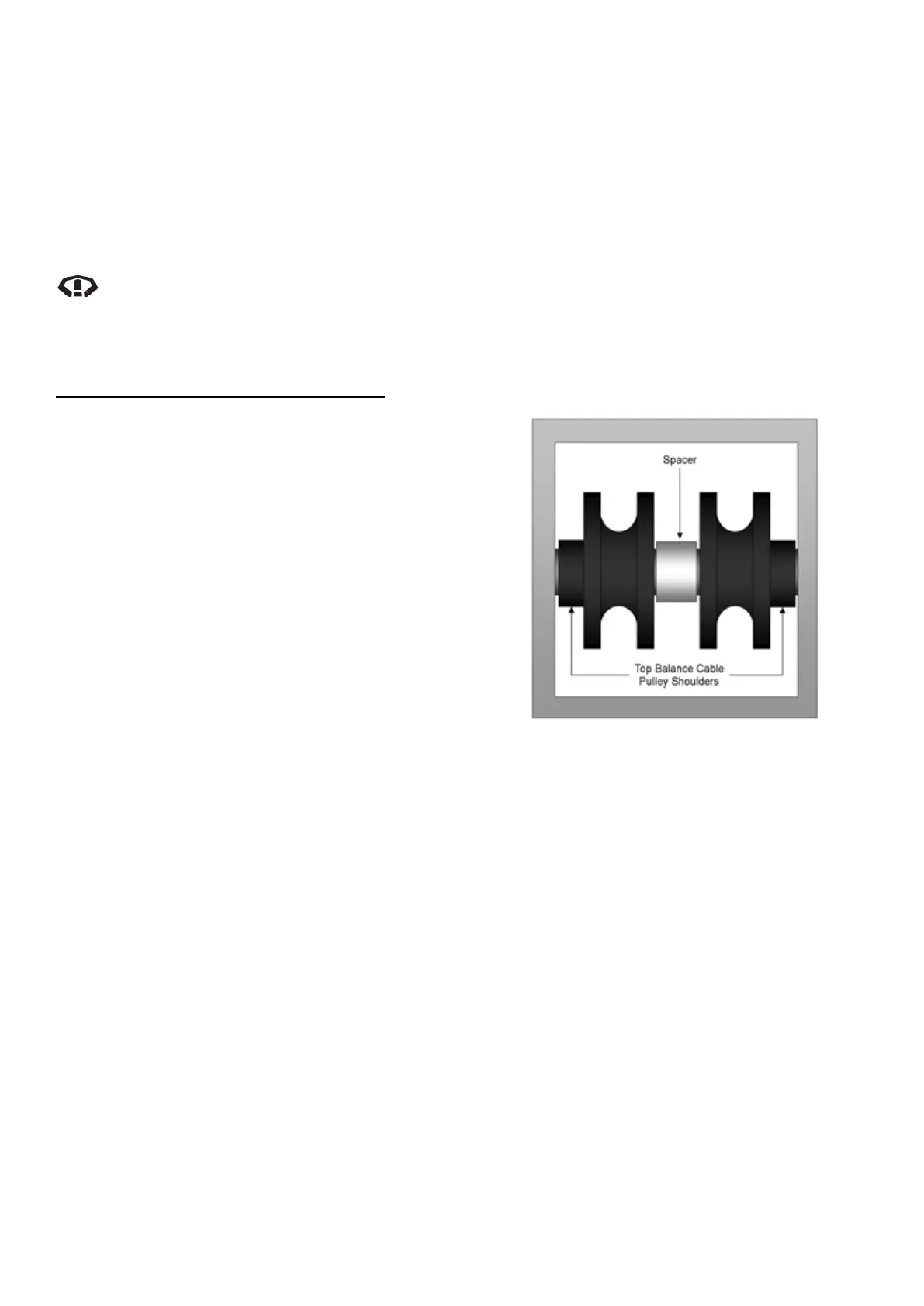
12. Lubricate the internal diameter of the new top pulleys and spacer with grease and fit the new top
pulleys and spacer onto the pulley pin with the orientation of spacer in the centre with a top pulley
on either end with the shoulders facing outwards. Refer to Diagram 37
13. Refit the items in order and secure
a. Top plate to post (bolts)
b. Overhead beam to top plates (bolts)
c. Remove cable tie from limit switch cable then refit limit switch to control post (screws)
d. Limit sensor bar to overhead beam (nyloc nut)
Diagram 37 – Top Balance Cable Pulleys
(Shoulder Outwards) and Spacer (Centre)
Orientation