20
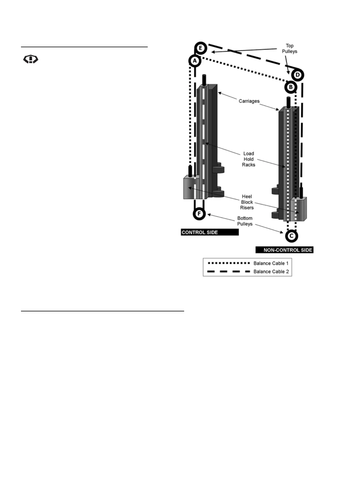
Diagram 36 – Balance Cable Layout
BALANCE CABLE & PULLEY REPLACEMENT
Balance Cable & Bottom Pulley Removal
Do not operate hoist without balance
cables.
Refer to Diagram 36 (Balance Cable Layout) and
Diagram 2 (Isometric View of M245 Hoist)
1. Raise the hoist and lock on first lock position.
2. Remove cylinder covers
3. Starting with Balance Cable 2 on the Control
Side, hold the cable end at the top of the load
hold rack with 9/16” open-ended spanner,
remove the cable Nyloc nut with Deep (24
mm) Socket and Ratchet.
4. Remove the retaining circlip and bottom
pulley (F) from the bottom of the post and
check condition.
5. Pull the loose cable end down out through
the bottom of the load hold rack.
6. Pull the cable out of the top over top pulley
(D) and feed the loose cable end into the
overhead beam assembly.
7. At the bottom of non-control carriage at the
heel block riser, remove the nut from the
opposite cable end.
8. Now that both ends of Balance Cable 2 are
free, pull the entire balance cable over the
top pulley (E) and up out through the top of
the control post.
9. Repeat Steps 3-8 for the Non-Control Side,
Balance Cable 1 and pulleys (A), (B) & (C).
New Balance Cable and Bottom Pulley Replacement
Refer to Diagram 36 (Balance Cable Layout) and Diagram 2 (Isometric View of M245 Hoist
1. Starting with the control post, feed cable end from new Balance Cable 2 down the centre of the top
of the control post over pulley (E) down and out through the hole in the heel block riser closest to
the load hold rack.
2. Run this cable end up inside the load hold rack and fit the Nyloc nut.
3. Feed the loose end of the cable through the overhead beam assembly, over pulley (D), down inside
the post until it protrudes through the bottom of the non-control heel block riser
4. Wind the Nyloc nut onto the loose end of this balance cable so 15-20mm of cable end thread is
protruding from the end of the Nyloc nut.
5. Refit existing bottom pulley (F) and retaining circlip if in good condition or replace with new
components if necessary. Note that the small shoulder of the pulley should be towards the inside of
the post, the flat side should be facing outwards to the circlip. Ensure balance cable is firmly sitting
in the groove of the pulley.
6. Repeat Steps 1-5 for the Non-Control Side, new Balance Cable 1 and pulleys (A), (B) & (C).
7. Check balance cables are;