12
Cylinder Fitting
Cylinder Fitting is almost the same process as the Cylinder Removal process in reverse. Please familiarise
yourself with the cylinder removal process before continuing.
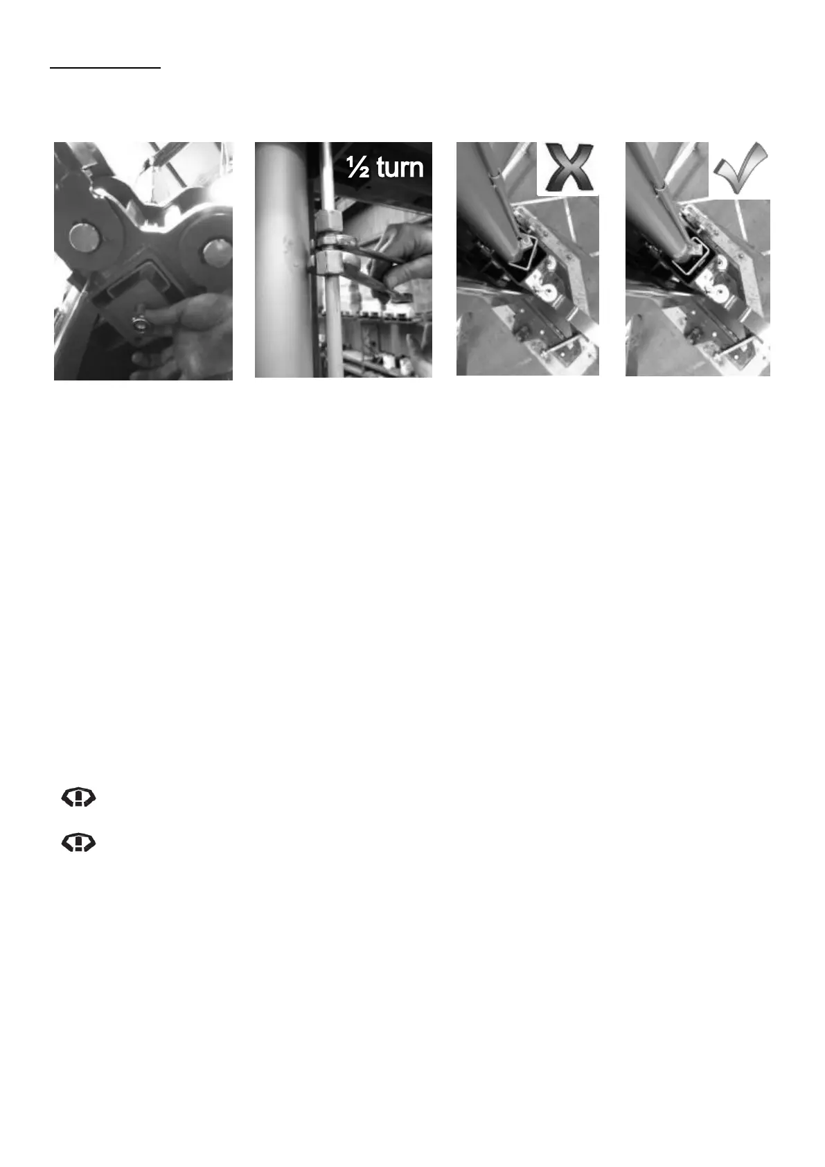
Diagram 15 – Hand fitting
Nyloc Nut
Diagram 16 – Attaching
New Hydraulic Fitting
Diagram 17 – Cylinder
incorrectly aligned to
Carriage
Diagram 18 – Cylinder
correctly aligned
square with Carriage
1. Ensure to plug the cylinder oil line (plug should be supplied with the cylinder) this will prevent
movement of the rod when handling the cylinder. Refer to Diagrams 12 & 13
2. Remove the nyloc nut from the end of the cylinder rod, and fit rod end down into the centre of the
carriage. Refer to Diagram 14
3. By hand, start the nyloc nut onto the cylinder piston rod end. Refer to Diagram 15
4. Continue to tighten with 27mm socket and impact gun used in short bursts until nut is firmly
tightened.
5. Loosen off nyloc nut by a ½ turn to allow some clearance for movement of the cylinder.
6. Loosen the 2.5 mm locking grub screw (max. 2 turns) and remove the cylinder end cap. Refer to
Diagram 7
7. Remove the plug from cylinder oil line.
8. Pull the cylinder barrel up and feed through the hole in the top plate at the top of the post, then while
holding the cylinder barrel, place wedge/packers between the top of the carriage and bottom of the
cylinder barrel. Refer to Diagram 9
9. Refit the cylinder end cap (firmly hand tighten) to the cylinder barrel and secure by tightening the
2.5mm locking grub screw.
NOTE: When removing or refitting the cylinder end cap, ensure the O-ring is maintained in
position at the top of the thread. Refer to Diagram 8
NOTE: When reassembling hydraulic fittings, re-apply the same torque, do not overtighten.
10. Connect the oil line to the new cylinder, firmly hand tighten, then using spanners, tighten a further
1/2 turn exactly. Refer to Diagram 16. If reassembling, the fittings should return to the same torque;
this can be achieved by marking the fittings for alignment. Refer to Diagram 3
11. Ensure the cylinder is positioned with brackets square to the carriage. Refer to Diagrams 17 & 18
12. Clean up any oil that has leaked onto the floor or the hoist. Make sure to check and clean inside the
post, under the carriage.
13. Remove wedge/packers under cylinder barrel and fit the bottom cylinder cover only.
14. Remove ‘F’ Clamp and reconnect electrical power supply to the hoist.
15. Complete bleeding of hydraulic system before fitting top cylinder cover.