18
f. Restart Balance Cable Adjustment procedure.
8. Raise the hoist 50mm and replace 90mm Pad Extensions.
9. Perform Balance Cable Adjustment check.
10. Set hoist onto first lock and replace the bottom cylinder covers from both posts
11. Lower hoist to ground and perform Lock Release Cable adjustment.
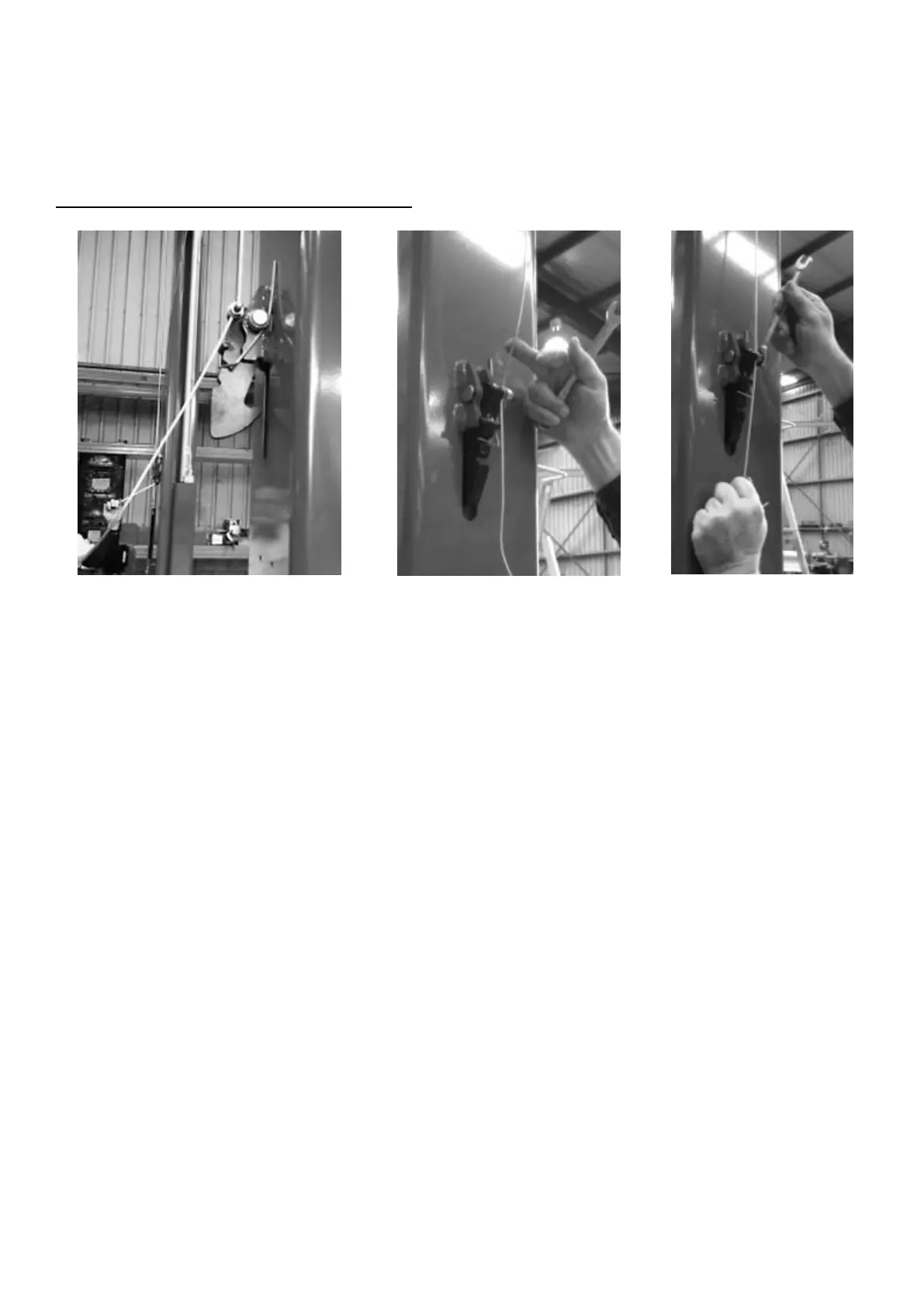
Lock Release Cable Adjustment Procedure
Diagram 31 -Checking Lock
Disengagement
Diagram 32 - Checking Lock
Release Cable Tension
Diagram 33 - Adjusting
Lock Release Cable
Tension
1. Remove the Release Cable Covers.
2. Raise the hoist off the locks.
3. Lubricate the locking toggle pivots and lock release cable pulley shafts then check they all pivot
freely.
4. Check the return springs are in good condition and positively engage locking toggles.
5. Hold down the lock release lever fully and compare the disengagement of the non-control lock to
the control side. The non-control side lock should retract as much or more than the control side,
Refer to Diagram 31, if not go to Step 8.
6. Set hoist onto first lock and hold down the hydraulic release lever for 10 seconds.
7. Check the tension of the lock release cable. Refer to Diagram 31
a. If loose, go to Step 8.
b. If tight, go to Step 12
8. Loosen off the clamping nut on the non-control side lock. Refer to Diagram 33