244 • Section 10 — Chassis Information Cayman 2006
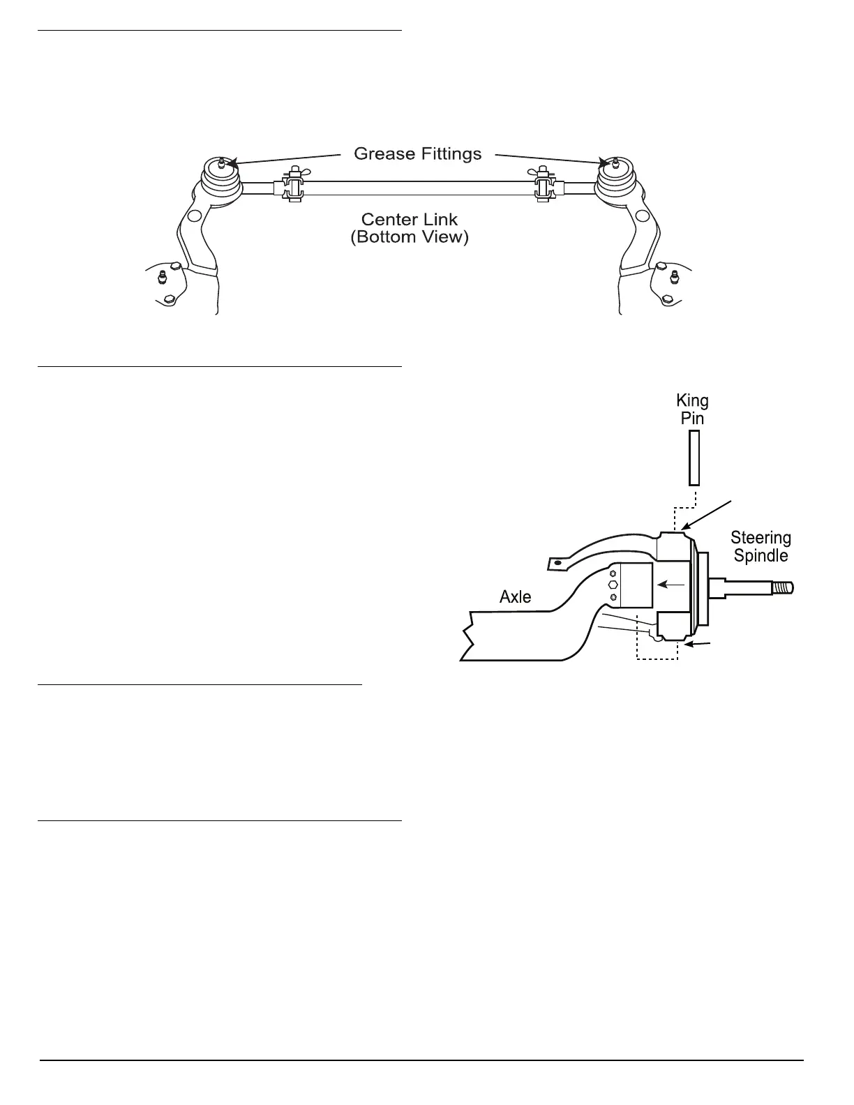
Center Link
The center link is located on the backside of the steer axle. The center link attaches the two wheels together
causing the right front to track with the left front. Greasing interval is every six months or 5,000 miles.
Steering Spindles
The steering spindles attach to the front axle and
pivot on the kingpin. The wheel end assembly and
brake system attach to the spindle. There are upper
and lower lubrication points for the kingpin. The drag
link attaches to the roadside spindle. After initially
lubricating the roadside and curbside kingpins, rotate
the steering assembly lock to lock (full left to right)
then move assembly back to center. This purges
remaining air pockets. Continue lubricating the
kingpins until new grease purges with no air pockets.
Greasing interval is every six months or 5,000 miles.
Control Arm Bushings
Control arms align the axles perpendicular with the frame. The panhard bar controls side to side motion of the
axles in the frame. Control arm bushings and panhard bar bushings do not require lubrication.
Steering Gear
The M-100 series Sheppard steering gear requires no maintenance. Using hydraulic pressure to assist rotating
the output shaft of the steering gear provides power steering. Located at the end of the input shaft of the steering
gear is a poppet valve and worm drive. The poppet valve directs the hydraulic fl uid pressure to a type of spool.
There are worm drive threads in the center of the spool. When in the center position, pressurized hydraulic
fl uid bypasses the spool. When a turn is made, the poppet valve shifts to one direction or the other, directing the
hydraulic pressure to one side of the spool depending on turning direction. The hydraulic fl uid is then cooled
before returning to the reservoir. Inspect for signs of leakage when performing fl uid level checks. Changing the
hydraulic fi lter at regular intervals will help ensure trouble free operation.
090354b
Upper
Lubrication
Points
Lower
Lubrication
Points
090414





 To Next Page