76347-281 • 12-08 3.49
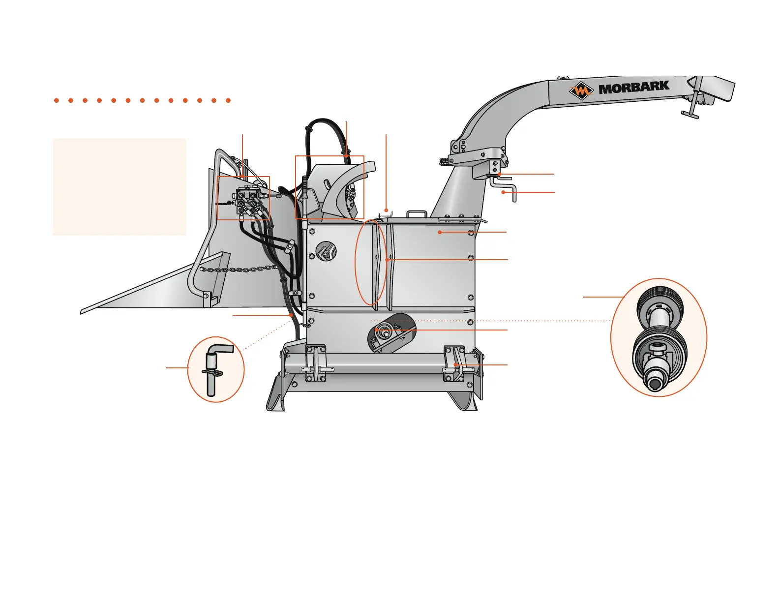
PTO Right View
5
2
9
Valve bank
bl
Figure 3.29
1. Valve bank: Main controls needed to operate the chipper.
2. Yoke : Housing for the feed wheel.
3. Hood locking pin: Secures hood and engages hood safety switch.
Important safety feature.
4. Discharge locking pin: Locks discharge chute in position.
5. Manual swivel discharge crank: Used to manually rotate the discharge
chute 360º.
6. Hitch plate: Protects operator from moving parts and is the mount for
the upper link arm. Remove this plate when doing maintenance to
interior components.
7. Upper link arm hook-up: The upper link arm attaches here. It is used to
stabilize and level the machine before operating. (Upper link arm not supplied.)
8. PTO drive shaft: Transmits power from the tractor’s engine to the chipper
drum drive shaft.
9. Chipper drum drive shaft: Powers the chipper drum. The PTO drive shaft
attaches here.
10. Pivot arm mounting bracket: The tractors pivot arm attaches to this
mounting bracket.
Yoke locking pin
8
Chipper drum
drive shaft
Hood
locking pin
7
Manual swivel discharge crank
3
Yoke
4
Discharge locking pin
Pivot arm
mounting bracket
Upper link arm hook-up
PTO drive shaft
Drum locking pin
(located next to the
yoke locking pin)
bm
1
bk
All PTO components that are
different from the standard
M15R are covered in this
section. See the standard
M15R for components not
covered in this PTO section.
6
Hitch plate
The Basics
Features and Function • The Basics, PTO
 Loading...