4.16 76347-282 • 12- 08
Knife Anvil
DANGER
Failure to lockout the machine (e.g. yoke, shut power off)
will result in unexpected operation and cause serious injury
or death. Always lockout the machine before conducting
maintenance (see Section One, Safety Lockout Procedure).
A rotating chipper drum can pinch body parts, entangle
loose clothing, jewelry, and long hair which will result in
cuts, mutilation, serious injury, or death. Shut down the
engine, wait for the chipper drum to completely stopped
rotating and insert the drum lock pin before initiating
maintenance.
NOTE
Incorrect clearance between a chipper knife and anvil will result in poor
chipping performance, damage to the chipper knives, and undue stress
on the chipper. Always maintain the proper knife-anvil clearance.
The anvil is located under the machine, and behind the infeed. The anvil and
chipper drum work together in chipping the brush, therefore it is important
the clearance between the anvil and knife are accurate. See figure 5.19 for the
anvil location.
To ensure maximum efficiency of the chipping operation the anvil must be
properly maintained. It is important to follow these guidelines to ensure
efficient chipping:
• Keep the anvil square
• Maintain the proper clearance between the chipper knife and anvil
• Two people are required to adjust the anvil
Before inspecting or maintaining the anvil:
1. Raise the yoke and insert locking pin (see Lockout Procedure).
2. Follow steps 1-4 in Chipping Cycle Section to shut-down the machine.
Inspect the anvil:
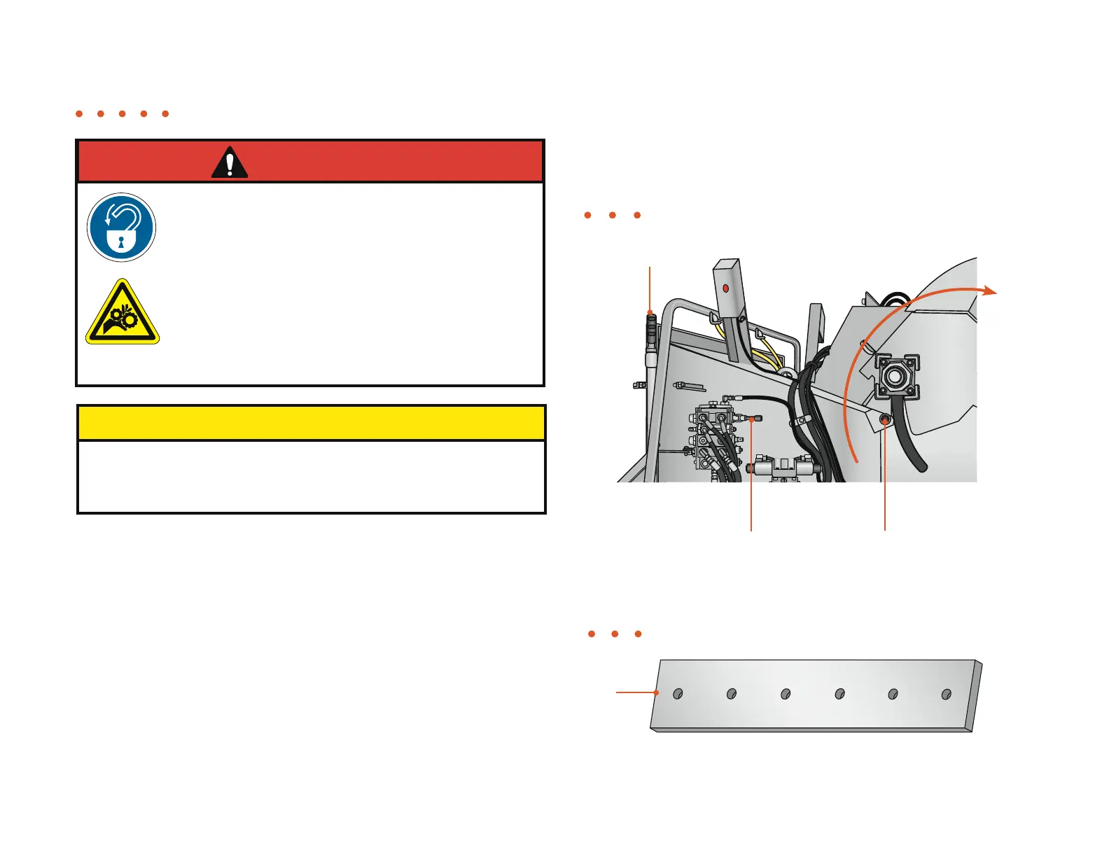
1. Inspect the anvil for wear and damage. The anvil edge should be square.
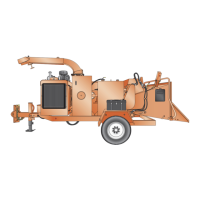
Yoke locking pin goes through the infeed
housing and is locked into place by a
hitch clip on the left side of the machine
Figure 4.16
Lift the yoke by activating the
yoke valve bank handle
2. Check the torque on the bolts that hold the anvil. Tighten if necessary
(see torque chart).
Figure 4.17
Anvil
Yoke locking pin
General Maintenance • Knife Anvil
 Loading...