ENGLISH
Fig. 11
- Get off the tractor and wait until all moving parts have
come to a complete stop.
Fig.10:
- Fold the front part of the protective cover upwards, turning
the front holder Z after having disengaged the side safety
lock (25 fig. 1).
- Fit pin K into the crossbar return (remember to remove it
when the machine is required for work).
- Get back on the tractor and close the mowing bar by
operating the tractors valve system, then hydraulic closing
cylinder C until safety clip A has fastened.
- Chain S should be detached from its work position (fig. 6)
and connected to the bar in point B using pin N and plug R,
to ensure safety during transport.
WARNING
It is absolutely essential to fit the safety chain in position
before transporting the machine on the roads.
During transport with the machine raised, always make
sure that the control lever is locked to prevent the
machine itself from accidentally lowering.
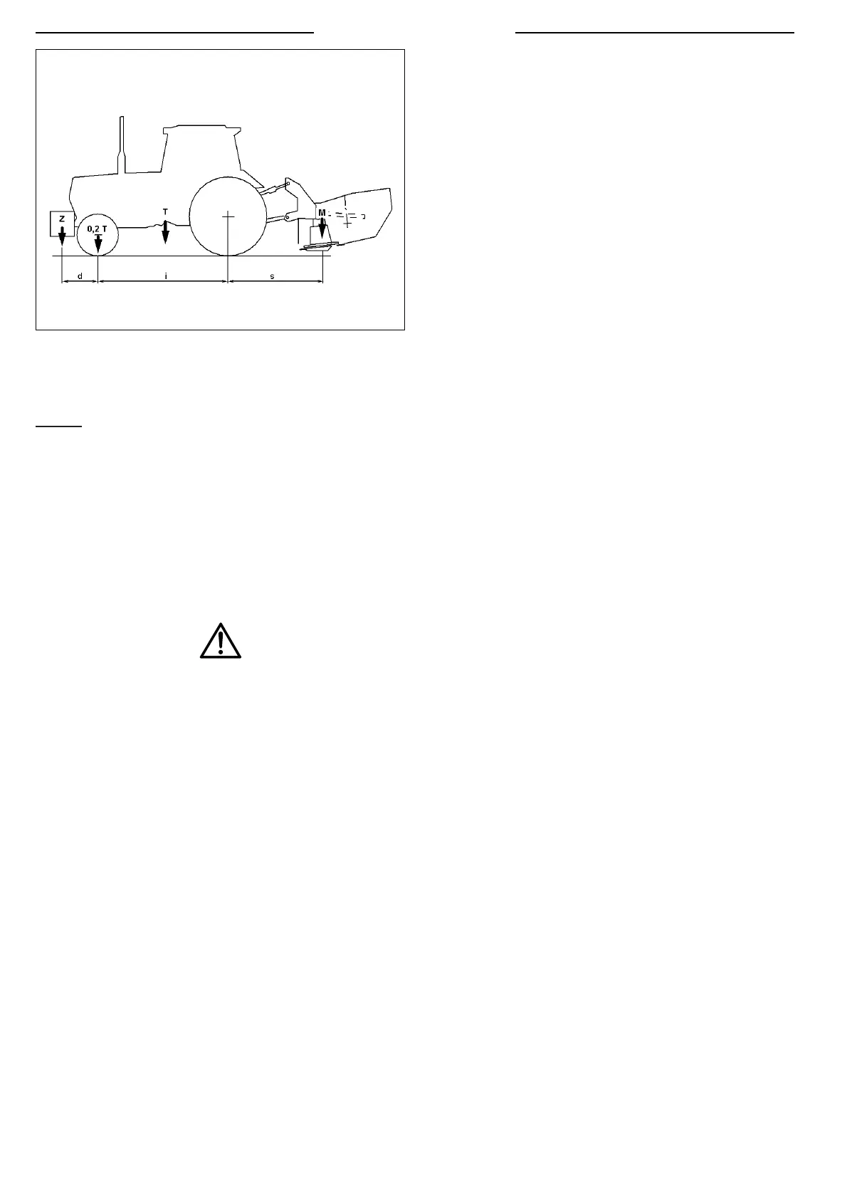
3.4 HOW TO CHECK THE LIFTING CAPACITY
AND STABILITY OF THE TRACTOR
Check the lifting capacity and stability of the tractor by means
of the following formula. Apply ballast at the front if necessary.
CAUTION
It is obligatory to check the lifting capacity and stability
of the tractor to prevent it from tipping up and/or losing
wheel grip.
M X s < 0.2 T X i + Z (d + i)
M < 0.3 T
(fig.11):
i = tractor wheelbase
d = distance of the front axle from the ballast
s = rear axle overhang of the machine
T = weight of the tractor + 75 kg (operator)
Z = weight of the ballast
M = weight of the machine
3.5 ADJUSTMENT
Correct adjustment of the work height of the machine will
allow you to work with excellent results. It also improves the
efficiency of the machine-tractor complex, notably reducing
the wear on the knives.
WARNING
Park the tractor on flat ground to prevent the side load
of the machine from bearing on the rods. Stop the engine
and apply the brakes before making the adjustments.
Adjust spring 1 by means of check nut C1 to lighten the bar
on the inner side (X). Adjust spring 2 by unscrewing check
nut C2 and using rod P (remember to lock check nut C2
once the adjustments have been made) so as to lighten the
bar on the outer side (Y) fig.12.